Strain Image Display Systems

a display system and image technology, applied in the field of strain image display system, can solve the problems of increasing the computational cost of improvement, affecting the interpretation of data, and affecting the quality of data, so as to improve the interpretability of the display and improve the quality of data

Inactive Publication Date: 2010-06-03
CAMBRIDGE ENTERPRISE LTD
View PDF7 Cites 21 Cited by
  • Summary
  • Abstract
  • Description
  • Claims
  • Application Information

AI Technical Summary

Benefits of technology

[0016]Broadly we will describe various aspects of a novel interface concept that we have developed to support a wide-ranging clinical trial of ultrasonic strain imaging. The new interface tackles numerous issues, including those mentioned above, to improve the quality of data that clinicians can acquire, and to improve the interpretability of the display. We present results exemplifying all of these aspects in application to real scan data both from in vitro and from in vivo targets.
[0017]According to the present invention there is therefore provided a method of displaying strain image data for an imaged object, the method comprising: capturing strain image data defining deformation of said object over an imaged region of said object; determining local image quality data, said local image quality data comprising a measure of the quality of said strain image data varying over said imaged region; and displaying a representation of said strain image data for said imaged region of said object, using said local image quality data to provide a visual indication of the quality of said displayed representation varying over said imaged region or to improve a quality of said displayed representation of said strain image data.

Problems solved by technology

The window matching approach to deformation estimation is sometimes problematic: pre- and post-deformation windows often match poorly, because deformation may not be negligible on the scale of the individual windows.
Deformation data from adaptive strain estimators are measurably less noisy than standard displacement estimation, but the improvement is accompanied by a considerable increase in computational cost.
However, one of the engineering challenges in strain imaging is the development of a suitable clinical interface.
The aforementioned issues concern how we present information.
Strain measurements can be converted into stiffness estimates if the stress field is known, but it is highly unlikely that this can be inferred from static (or quasistatic) deformation data without reducing the resolution and imposing limiting assumptions.
Furthermore, such assumptions are unlikely to hold even approximately under in vivo scanning conditions, especially not with freehand scanning.
On the other hand, strain images can in themselves sometimes be misleading, because an interpretation of low strain as indicating relatively high stiffness may be erroneous if the stress field varies substantially throughout the tissue.
In practice, an often more severe obstacle in freehand strain imaging is the basic challenge of achieving an acceptable strain estimation signal-to-noise ratio.
Although many frames individually produce good images, typically a substantial fraction (and sometimes a majority) of frames may be difficult to interpret because of high estimation noise.

Method used


Image

  • Strain Image Display Systems
  • Strain Image Display Systems
  • Strain Image Display Systems

Examples


Embodiment Construction

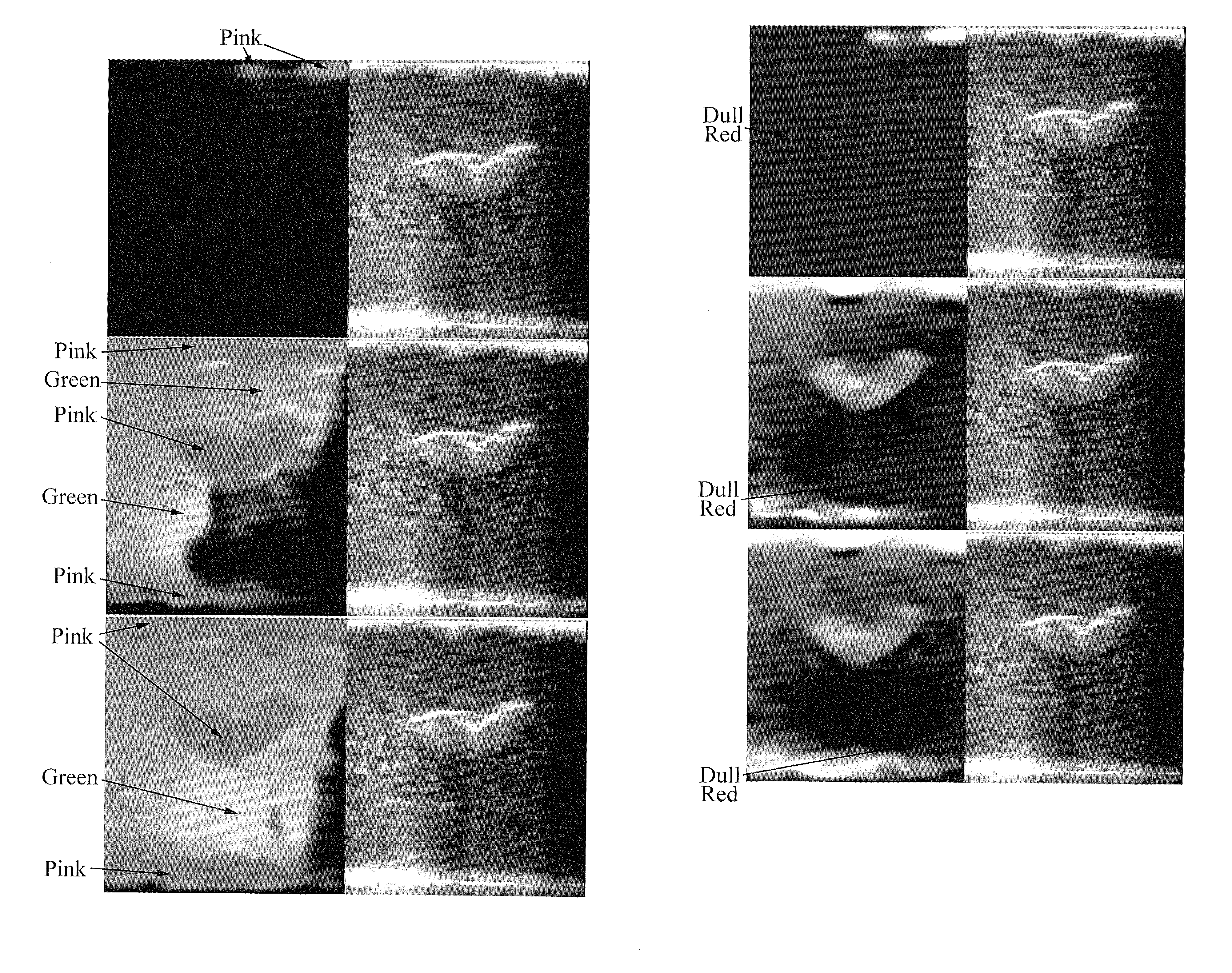
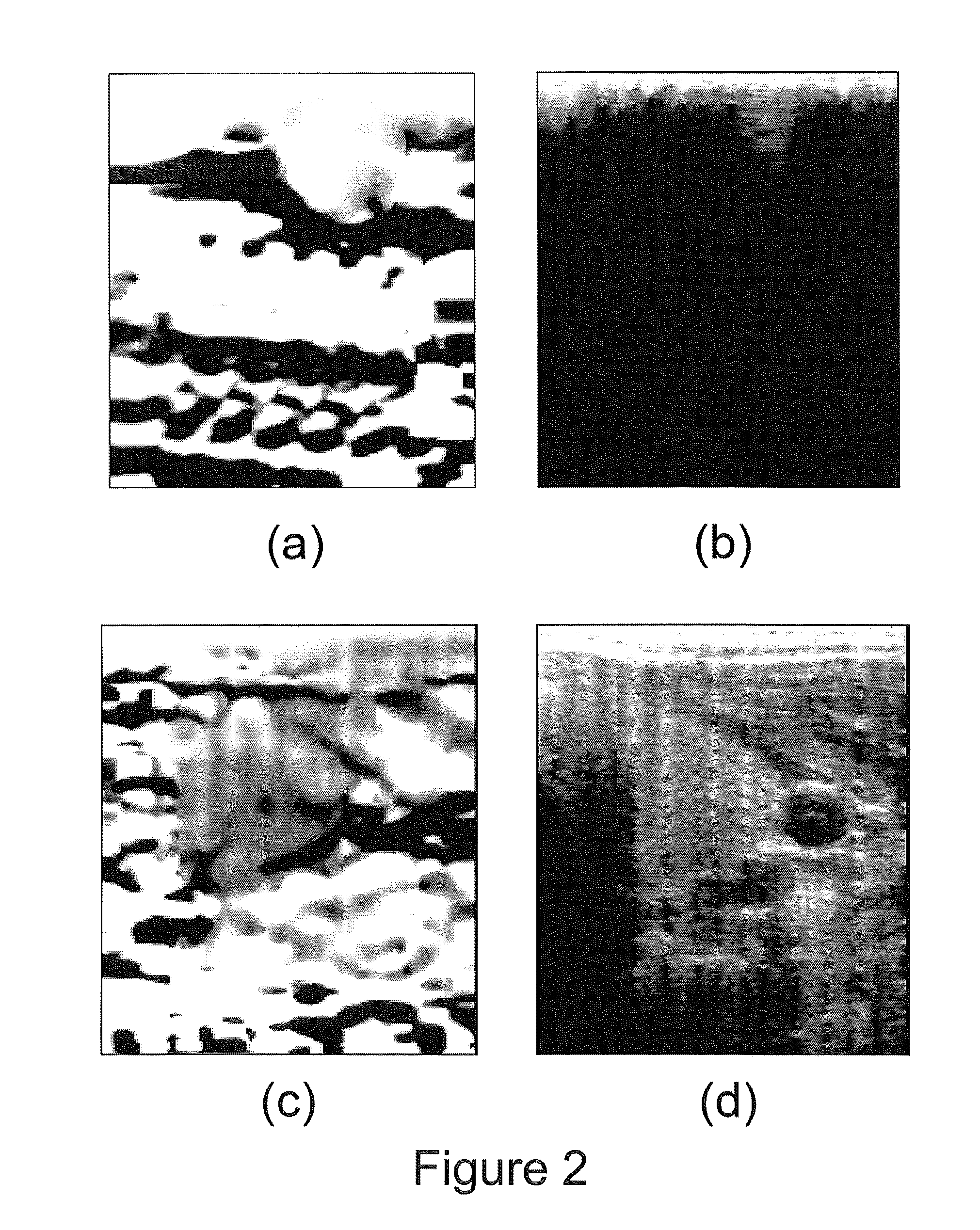
[0047]Broadly, we will describe an interface for freehand strain imaging, which has been designed to support clinical trials investigating the potential of ultrasonic strain imaging for diagnostic purposes across a broad range of target pathologies. The aim with this interface is to make scanning easier, and to help clinicians learn the necessary scanning technique quickly, by providing real time feedback indicating the quality of the strain data as they are produced. The images are also easier to interpret, because data at unacceptably low signal-to-noise ratios do not reach the display. The main components of the interface are novel normalisation, persistence and display methods. These not only present data in a more meaningful format, but the level of noise in the displayed images may actually be reduced compared to other methods that use the same strain estimates with the same level of persistence.

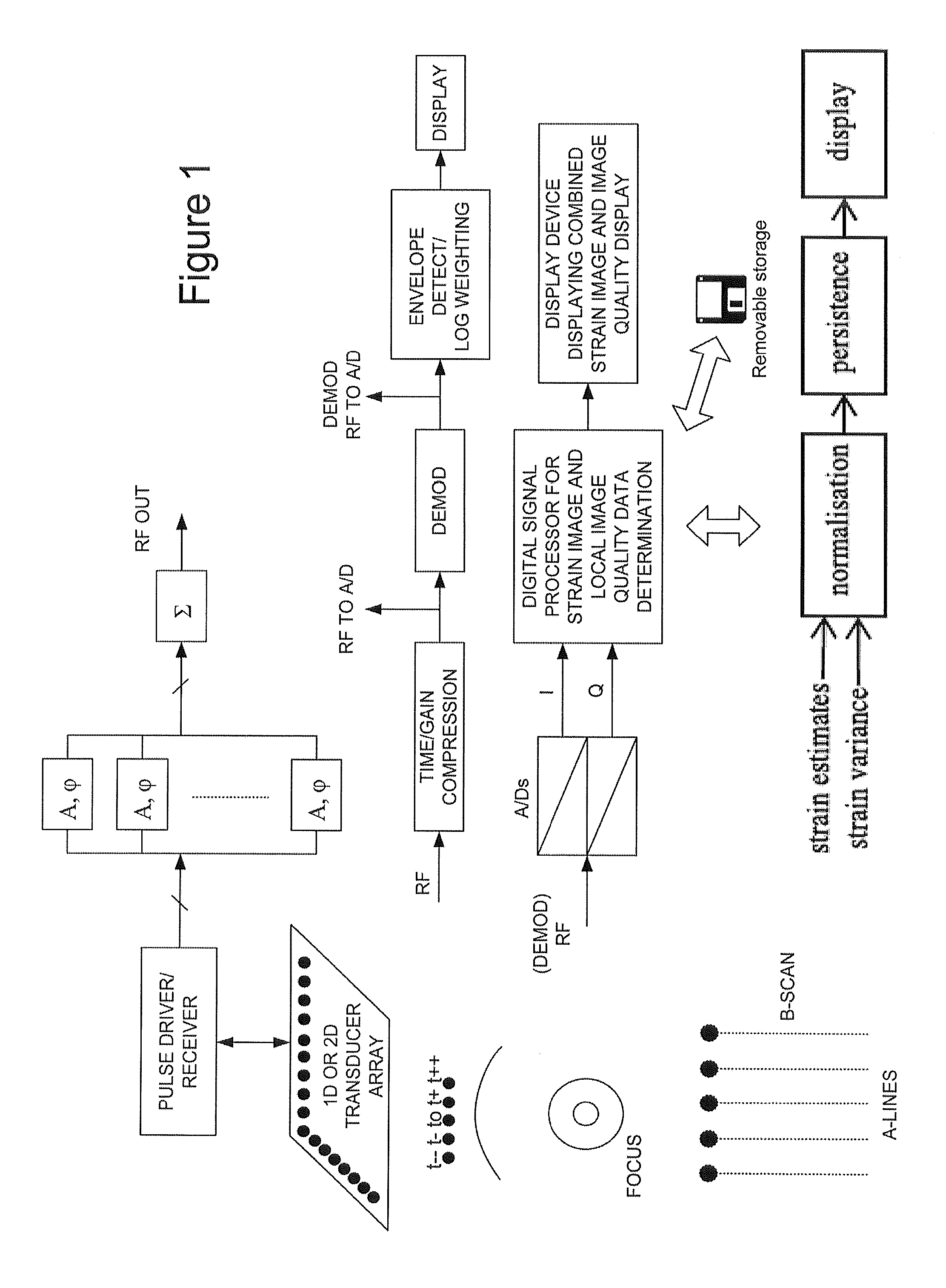
[0048]FIG. 1 shows an outline block diagram of an ultrasonic imaging system config...


PUM


Abstract

A method of displaying strain image data for an imaged object, the method comprising: capturing strain image data defining deformation of said object over an imaged region of said object; processing said strain image data to determine local image quality data, said local image quality data comprising a measure of the quality of said strain image data varying over said imaged region; and displaying a representation of said strain image data for said imaged region of said object, using said local image quality data to provide a visual indication of the quality of said displayed representation varying over said imaged region or to improve a quality of said displayed representation of said strain image data.

Description

FIELD OF THE INVENTION[0001]This invention relates to methods, apparatus and computer program code for displaying strain images.BACKGROUND TO THE INVENTION[0002]Ultrasonic strain imaging is an emerging technique, which is likely to have numerous applications in the clinical examination of soft tissues. Here we are primarily (but not exclusively) interested in the subset of elasticity imaging techniques that are often grouped together as “static” (or “quasistatic”) strain imaging. In this paradigm, small tissue deformations are caused by contact with the ultrasound probe at the tissue surface; two or more ultrasound frames are recorded during this deformation, and some form of tracking is applied to the recorded ultrasound data to estimate tissue deformations, amounting to spatially-varying displacement fields. Spatial derivatives of such a displacement field are tissue strain, which indicates stiffness: there are sometimes further stages of analysis to estimate quantitative tissue p...

Claims


Application Information

Patent Timeline
Patent Type & Authority Applications(United States)
IPC IPC(8): G01S15/89G06K9/00
CPCA61B8/08A61B8/0825A61B8/463A61B8/485G01S7/5205A61B8/483G06T7/0012G06T7/0024G06T2207/10132G06T2207/30004G01S7/52071G06T7/30A61B8/00
Inventor LINDOP, JOEL EDWARDTREECE, GRAHAM MICHAEL
Owner CAMBRIDGE ENTERPRISE LTD
Why Eureka
Try Eureka