
Image processing system

a technology of image processing and computer generated graphics, applied in the field of image processing, can solve the problems of difficult to render computer generated graphics, difficult to achieve real-life effects, and difficult to add computer generated graphics into video scenes such that they appear to be realistically placed in three-dimensional space, etc., to achieve greater accuracy and realism.

Inactive Publication Date: 2010-06-03
SONY CORP
View PDF5 Cites 56 Cited by
  • Summary
  • Abstract
  • Description
  • Claims
  • Application Information

AI Technical Summary

Benefits of technology

[0006]The present invention provides a system in which an image processor is able to estimate the orientation of a camera from a video signal generated by the camera which is representative of a scene including a calibration surface on which is provided a number coloured elements from which corner locations can be derived. The invention takes advantage of the fact that the orientation of a surface comprising parallel lines can be determined from a two dimensional image of that surface by determining the point at which those parallel lines intersect on the plane of the captured image. Embodiments of the invention provide a mechanism by which the parallel lines can be identified by determining the location of corner features of the calibration surface by defining an area centred around each potential corner location and analysing a colour of points lying on a periphery of the defined area. This mechanism provides a particularly quick and efficient way of identifying the location of corners on the calibration surface which can be readily implemented and undertaken in real time. The present invention therefore has numerous applications but in particular allows for computer generated objects to be incorporated into images and video taken by the camera whilst allowing the orientation of the camera to be taken into account when rendering the computer generated object.
[0008]In this further embodiment, the position of the camera can be estimated in addition to the orientation of the camera. Therefore, both the orientation and the relative location of the camera can be determined. This embodiment allows, for example, computer generated objects to be combined with images captured by the camera with even greater accuracy and realism as both the location and orientation of the camera can be taken into account when rendering the computer generated object.

Problems solved by technology

Similarly, many modern films include a great deal of computer generated content which is intermixed with real-life actors and objects to achieve effects which would be impossible or very expensive to achieve in real life.
However, adding a computer generated graphic into a video scene such that it appears to be realistically placed in three dimensional space can be much more difficult, particularly if the position of a camera capturing the real-life scene is changing.
Furthermore, it can be difficult to render computer generated graphics so that they appear to be lit in the same manner as real-life objects in the scene.
However, this is time consuming and is not practical for applications which demand a computer generated object be realistically placed and lit in a video scene in real time.
However, it can be difficult to achieve realistic looking results if a virtual object is to cast a computer generated shadow on a real object.
In particular, it can be difficult to render the computer generated shadow such that it appears to be cast on the real object if there are one or more virtual light sources in the scene or where a computer generated object is to be inserted into a scene such that it should cast shadows caused by the virtual object occluding a real light source.

Method used


Image

  • Image processing system
  • Image processing system
  • Image processing system

Examples


Embodiment Construction

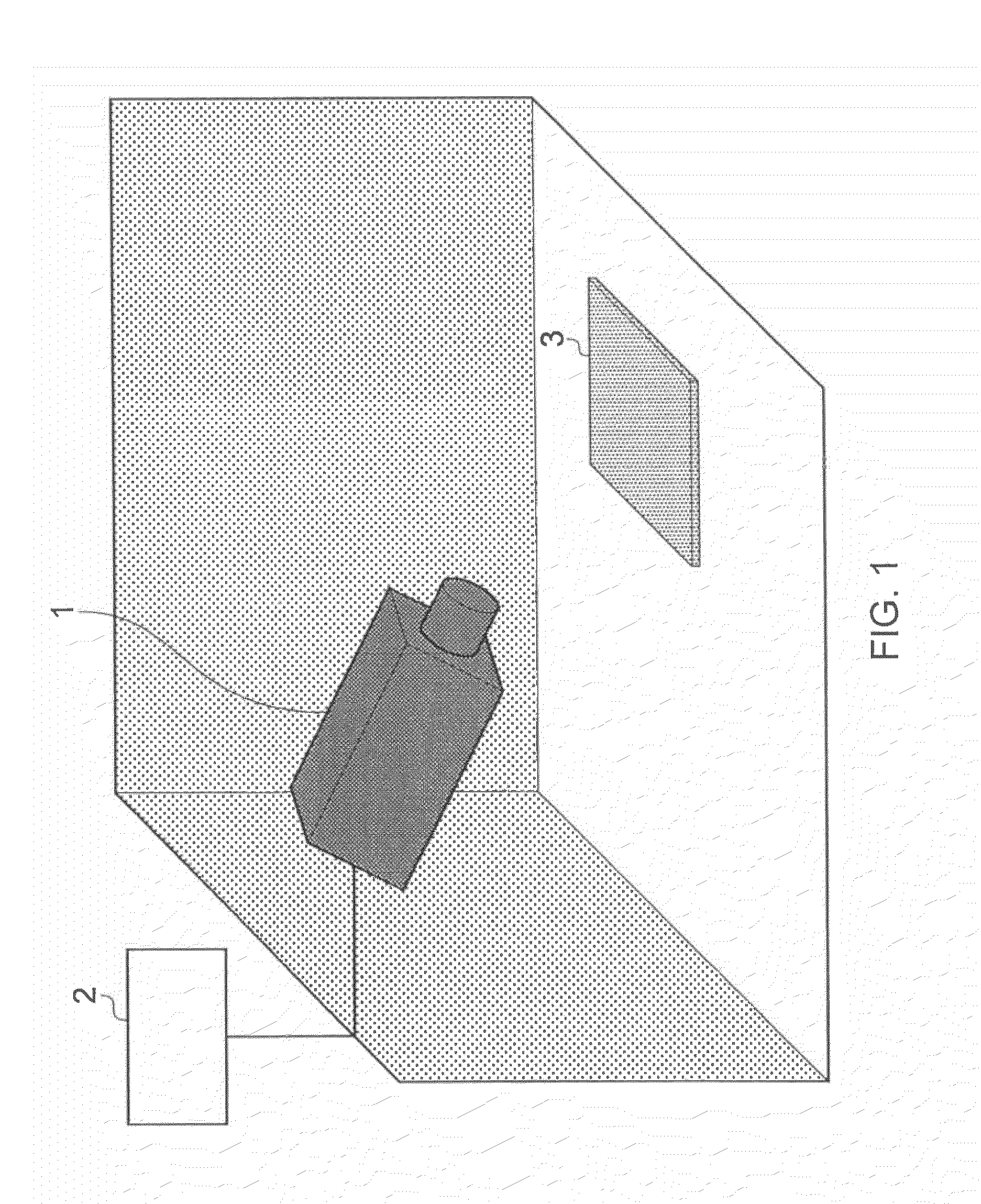
[0040]FIG. 1 provides a schematic diagram of an example of a system for determining camera parameters from a captured image. A camera apparatus 1 is provided which is capable of capturing image data, for example a video signal, representative of a scene as viewed by the camera 1. The camera 1 is connected to an image processor 2. Together the camera 1 and image processor 2 comprise an image processing apparatus. The camera is directed at a calibration surface 3. The camera 1 captures image data representative of the calibration surface 3 and communicates data corresponding to these images back to the image processor 2. The calibration surface 3 includes a calibration pattern. The image processor 2 analyses the images captured by the camera 1 of the calibration surface and uses information derived from the captured images of the calibration surface 3 to determine a set of parameters corresponding to the orientation of the camera 1 relative to the calibration surface 3.
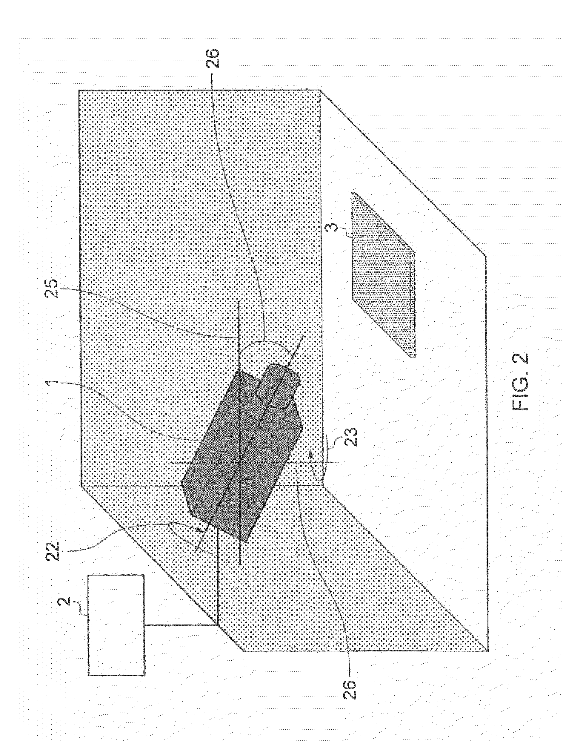
[0041]FIG. 2 il...


PUM


Abstract

An image processing system includes a camera, an image processor and a calibration surface. The calibration surface includes thereon a calibration pattern, the calibration pattern comprising a plurality of alternately coloured elements which provide a corresponding plurality of corners at locations on the calibration pattern at which more than two of the coloured elements adjoin. The corner locations define a first group of lines and a second group of lines, the lines in each of the group of lines are parallel with respect to each other and with respect to the calibration surface. The first group of lines is orthogonal to the second group of lines and the camera is operable to generate and communicate to the image processor a video signal representative of a scene as viewed by the camera, the scene including the calibration surface. The image processor is operable to detect from the video signal at least some of the corner locations and thereby identify the first and second group of lines of the calibration pattern, to extrapolate the lines from each group of lines to determine a presence and a location of a first intersection point on a plane of the scene as viewed by the camera at which the extrapolated lines from the first group intersect and a second intersection point on the plane of scene as viewed by the camera at which the extrapolated lines from the second group intersect, and to estimate from the presence and the location of the first and second intersection points one or more of an estimated roll angle value, an estimated pitch angle value and an estimated yaw angle value corresponding to a roll angle, pitch angle and yaw angle of the camera relative to the calibration surface. The detection of the corner locations by the image processor comprises identifying from the video signal a plurality of potential corner locations, defining an area of the scene as viewed by the camera centred around each potential corner location, analysing a colour of points lying on a periphery of each area, thereby estimating a likelihood that a corner is located at each potential corner location.

Description

FIELD OF THE INVENTION[0001]The present invention relates to image processing. More particularly embodiments of the present invention relate to methods of and systems for estimating camera parameters from a captured image.BACKGROUND OF THE INVENTION[0002]In many applications it is desirable to add computer generated graphics to enhance conventionally captured video images. For example, news broadcasts and televised weather forecasts frequently include computer generated content such as text banners, maps, backdrops and so on, which are added to conventionally captured video images of a human presenter. Such computer generated content can improve the clarity with which information is presented to a viewer and can be easily and conveniently edited and updated. Similarly, many modern films include a great deal of computer generated content which is intermixed with real-life actors and objects to achieve effects which would be impossible or very expensive to achieve in real life.[0003]I...

Claims


Application Information

Patent Timeline
IPC IPC(8): H04N17/00
CPCH04N5/2224G06T7/0044G06T7/74G06T7/80H04N5/142
Inventor WITT, SARAH ELIZABETH
Owner SONY CORP
Features
  • Generate Ideas
  • Intellectual Property
  • Life Sciences
  • Materials
  • Tech Scout
  • Unparalleled Data Quality
  • Higher Quality Content
  • 60% Fewer Hallucinations
Learn More