Digital integration with detector correction

a digital integration and detector technology, applied in tomography, instruments, applications, etc., can solve the problems of blurring in an axial direction, blurring of acquired images, etc., and achieve the effect of reducing motion artifacts and eliminating image blurring

Inactive Publication Date: 2010-06-03
TERATECH CORP
View PDF27 Cites 7 Cited by
  • Summary
  • Abstract
  • Description
  • Claims
  • Application Information

AI Technical Summary

Benefits of technology

[0003]The present invention relates to x-ray imaging systems in which the detector system output is sampled at a rate to reduce motion artifacts. Digital

Problems solved by technology

There are artifacts associated with the detectors delays response from the current exposure and the decay responses of previous exposures, which leads to blurring of the acquired im

Method used


Image

  • Digital integration with detector correction
  • Digital integration with detector correction
  • Digital integration with detector correction

Examples


Embodiment Construction

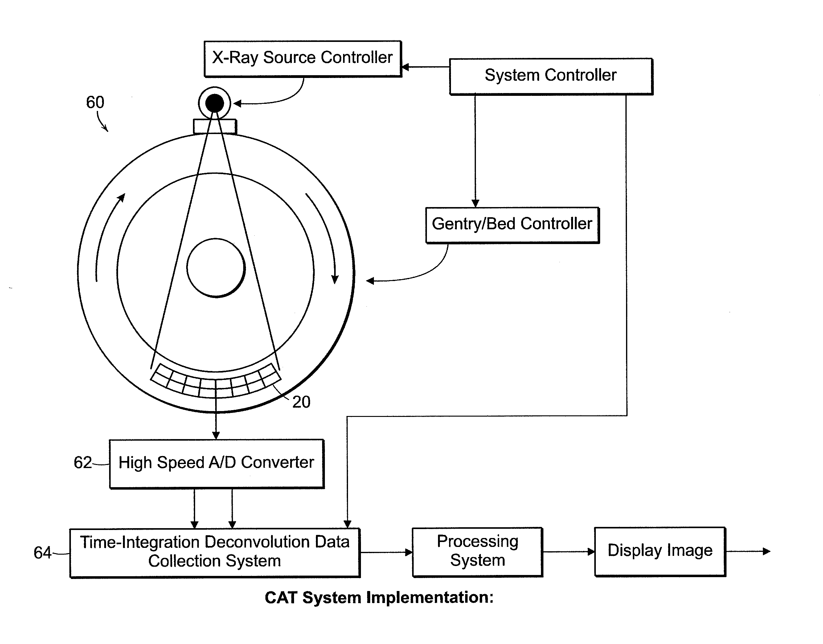
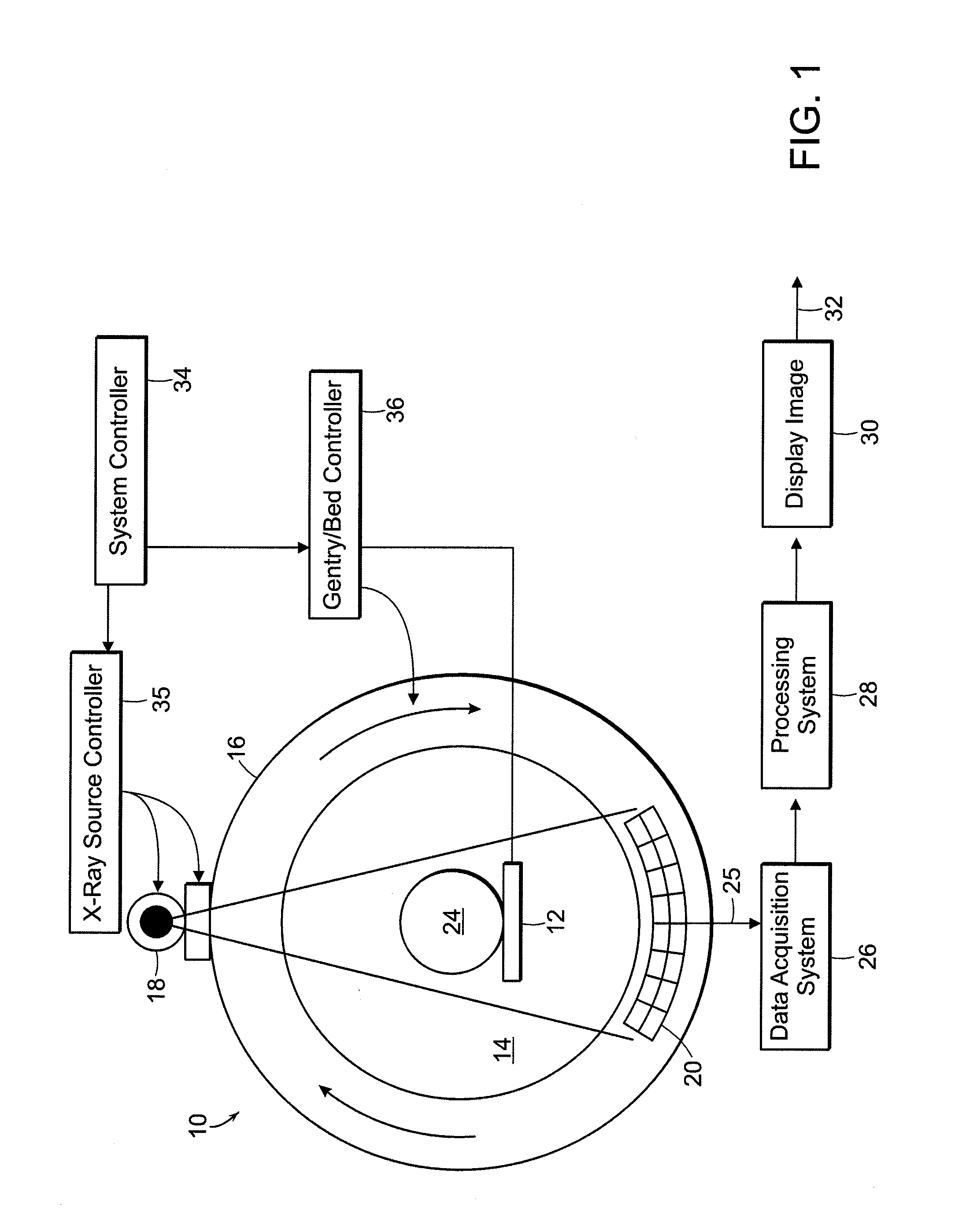
[0014]As can be seen in FIG. 1, a CT scanner 10 includes of an object table or support 12 which is positioned within the center opening aperture 14 of a frame 16 or gantry. A x-ray source 18 is mounted within the gantry 16 to one side of the opening aperture 14, and a detector array 10 is mounted to the second side of the aperture 14. During scanning, the x-ray source and the detector array are rotated around the object 24. CT relies on the measurement of attenuated x-ray transmission flux through the object from different rotation angles to form an image. The X-ray flux after attenuation by an object impinging on the x-ray detector and the attenuated x-ray flux is measured and recorded using a data acquisition system 26, data processing system 28 and display 30. The images can then be transmitted 32 via wired or wireless connection to data storage or a network. A system controller 34 is connected to the x-ray source controller 35 and the gantry and support controller 36. the data a...


PUM


Abstract

The present invention relates to systems and methods for reducing motion artifacts in x-ray imaging systems. The detector system output is sampled at a rate than the x-ray exposure rate to reduce blurring associated with motion of the detector and/or object being scanned.

Description

CROSS REFERENCE TO RELATED APPLICATION[0001]This application claims priority to U.S. Application 61 / 118,793 filed on Dec. 1, 2008 the entire contents of which is incorporated herein by reference.BACKGROUND OF THE INVENTION[0002]A CT or Computed Tomography scanning system can be used for many applications including imaging of the human anatomy in a medical imaging system as well as for baggage / container images in a security / inspection system. To form one frame of a CT image of a patent, for example, a scanner acquires roughly 1000 sequential X-ray exposures, each with 0.5 ms to 1 ms of exposure time. The X-ray transmission flux is measured at each of those 1000 exposures. The processed transmission flux measurements are then used to reconstruct an image which reveals the anatomical structures in a slice taken through the patient from the patient. There are artifacts associated with the detectors delays response from the current exposure and the decay responses of previous exposures, ...

Claims


Application Information

Patent Timeline
IPC IPC(8): H05G1/60
CPCA61B6/032A61B6/027A61B6/5264A61B6/4233
Inventor CHIANG, ALICE
Owner TERATECH CORP
Why Eureka
Try Eureka