
Packet-optical integrated switch without optical transponder

a technology of optical transponder and integrated switch, which is applied in the field of packagetoptical integrated switch without optical transponder, can solve the problems of increasing fabrication cost and installation cost due to repetition in configuration, and achieve the effects of reducing production cost, extending application range, and simplifying conversion

Inactive Publication Date: 2010-06-03
ELECTRONICS & TELECOMM RES INST
View PDF14 Cites 9 Cited by
  • Summary
  • Abstract
  • Description
  • Claims
  • Application Information

AI Technical Summary

Benefits of technology

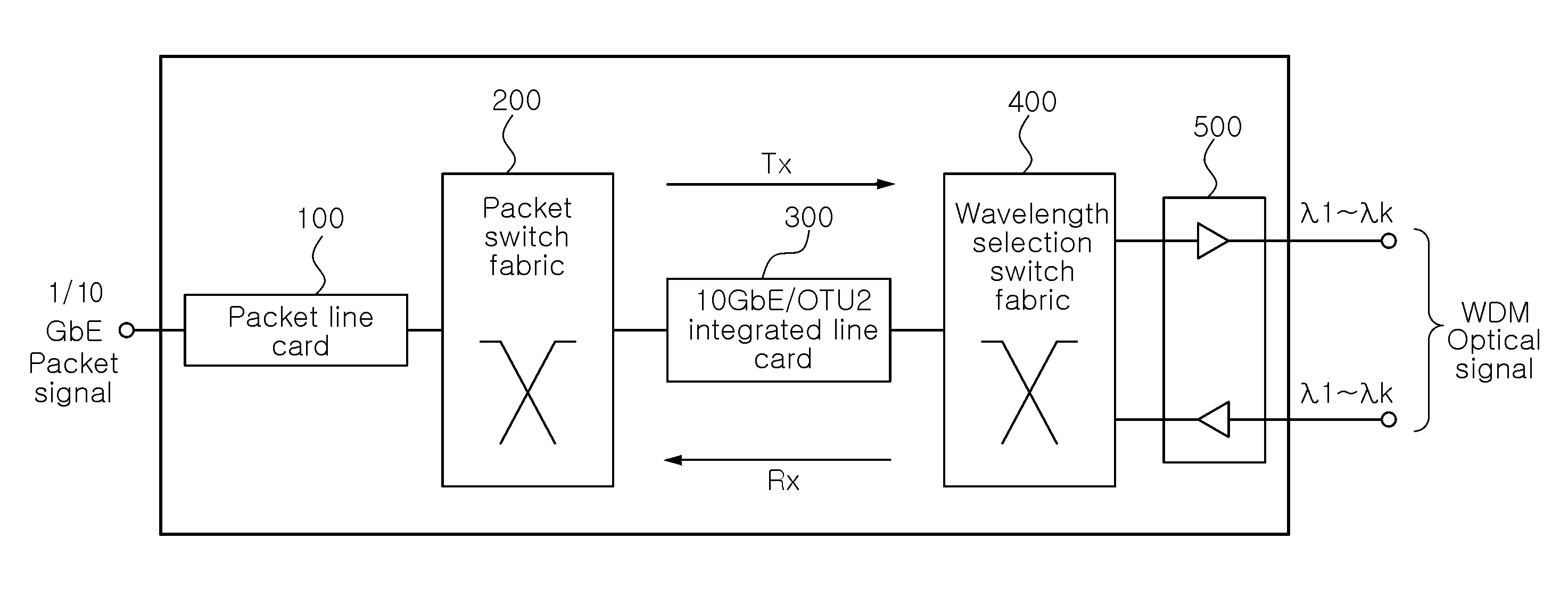
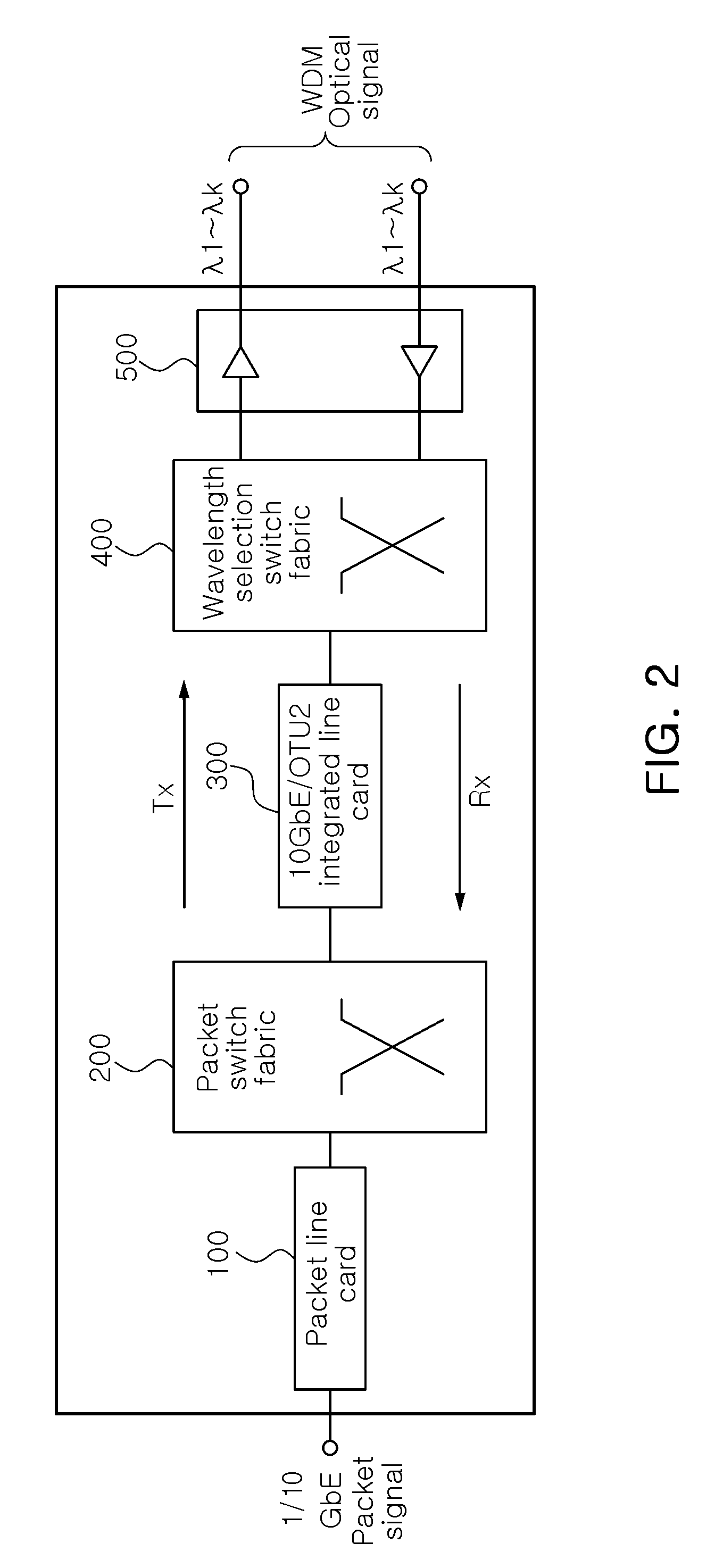
The present invention provides a packet-optical integrated switch without an optical transponder that simplifies the conversion and switching between Ethernet and optical transport unit (OTU2) signals. This switch offers flexibility and reduces production costs by integrating a line card of a packet switch with an optical transponder of an optical switch. The switch includes a packet line card, a packet switch fabric, a 10 GbE / OTU2 integrated line card, and a wavelength selection switch fabric. The switch can selectively generate an Ethernet or OTU2 optical signal by using a pre-set wavelength. The switch also includes an amplifying unit and a synchronization unit to improve the quality of the optical signal. The invention provides a flexible and cost-effective solution for applications that require Ethernet and OTU2 signals.

Problems solved by technology

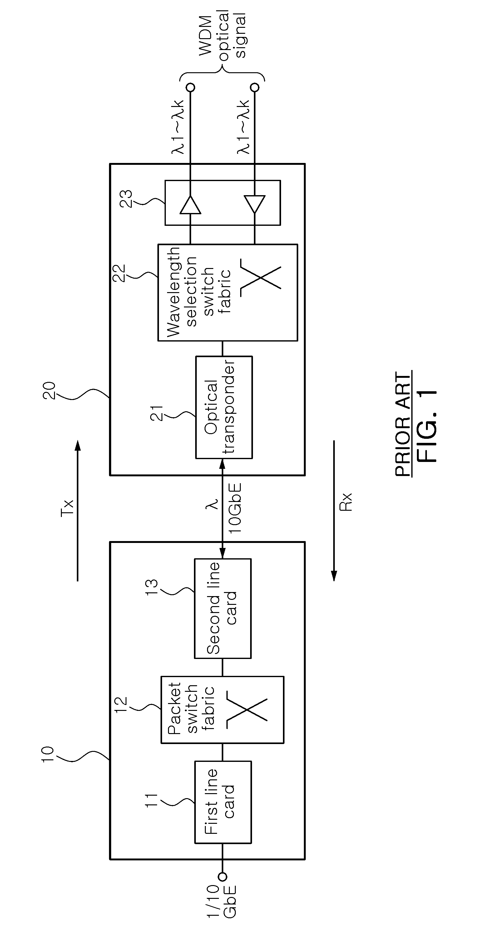
In this respect, however, interconnection between the related art packet switch and the optical switch requires the necessity of the presence of the line card in the packet switch and the optical transponder in the optical switch, increasing the fabrication cost and the installation cost due to the repetition in the configuration.

Method used


Image

  • Packet-optical integrated switch without optical transponder
  • Packet-optical integrated switch without optical transponder
  • Packet-optical integrated switch without optical transponder

Examples


Embodiment Construction

[0035]Exemplary embodiments of the present invention will now be described in detail with reference to the accompanying drawings. The invention may however be embodied in many different forms and should not be construed as limited to the embodiments set forth herein. Rather, these embodiments are provided so that this disclosure will be thorough and complete, and will fully convey the scope of the invention to those skilled in the art. In the drawings, the shapes and dimensions may be exaggerated for clarity, and the same reference numerals will be used throughout to designate the same or like components.

[0036]FIG. 2 is a schematic block diagram of a packet-optical integrated switch without an optical transponder according to an exemplary embodiment of the present invention. As shown in FIG. 2, the packet-optical integrated switch according to an exemplary embodiment of the present invention includes a packet line card 100, a packet switch fabric 200, a 10 GbE / OTU2 integrated line c...


PUM


Abstract

A packet-optical integrated switch without an optical transponder, includes: a packet line card configured to output an Ethernet packet signal to a pre-set output port; a packet switch fabric configured to transfer the packet signal from the packet line card to the output port previously set in a destination address included in the packet signal; a 10 gigabit Ethernet (10 GbE) / optical transport unit level 2 (OTU2) integrated line card configured to convert the packet signal from the packet switch fabric into an OTU2 optical signal having a pre-set wavelength; and a wavelength selection switch fabric configured to allocate the optical signal from the 10 GbE / OTU2 integrated line card to a pre-set wavelength division multiplexing (WDM) port by pre-set wavelength to exchange the optical signal to each port by wavelength, wherein the packet line card, the packet switch fabric, the 10 GbE / OTU2 integrated line card, and the wavelength selection switch fabric perform the reverse operations of the process, respectively.

Description

CROSS-REFERENCE TO RELATED APPLICATIONS[0001]This application claims the priorities of Korean Patent Application Nos. 10-2008-0121239 filed on Dec. 2, 2008 and 10-2009-0037575 filed on Apr. 29, 2009, in the Korean Intellectual Property Office, the disclosures of which are incorporated herein by reference.BACKGROUND OF THE INVENTION[0002]1. Field of the Invention[0003]The present invention relates to a packet-optical integrated switch applicable for a packet-optical transport network (P-OTN) system and, more particularly, to a packet-optical integrated switch without an optical transponder capable of simplifying conversion and switching between a packet signal of an Ethernet (10 gigabit Ethernet: 10 GbE) and an optical signal of an optical transport unit level 2 (OTU2) and reducing production costs.[0004]2. Description of the Related Art[0005]In general, a packet network technique and an optical transport network technique have been separately developed in different regions.[0006]As ...

Claims


Application Information

Patent Timeline
Patent Type & Authority Applications(United States)
IPC IPC(8): H04J14/00H04J14/02H04L12/56
CPCH04J14/0227H04L49/352H04J14/0256H04Q11/0005H04J14/0212H04L49/357
Inventor KIM, HONG JUCHOYOUN, JI WOOKLEE, HYUN JAEKIM, BUP JOONGKIM, SUN MEAHN, BYUNG JUN
Owner ELECTRONICS & TELECOMM RES INST
Learn More