
Device and method for supplying structural components to an assembly zone

Inactive Publication Date: 2010-06-03
AIRBUS OPERATIONS GMBH
View PDF6 Cites 37 Cited by
  • Summary
  • Abstract
  • Description
  • Claims
  • Application Information

AI Technical Summary

Benefits of technology

[0009]In accordance with an advantageous development of the device, at least two positioning towers are provided in each case on either side of the at least one side shell support. The large and thus mechanically labile side shells are thus retained securely and can be positioned in a sufficiently precise manner. Irrespective of the size of the side shells, the device preferably has six positioning towers, of which three are arranged within the assembly zone in each case on either side of the fuselage portion to be produced. By means of the positioning towers, two side shells which mirror one another can be spatially positioned in a largely free manner within the assembly zone.
[0022]Owing to the fact that the side shells have already been placed on a side shell support by the manufacturer, they can be aligned inside the device in a highly accurate manner in method step a). Since each of the side shells is transferred in method step b) to at least two positioning towers, the side shells can be largely freely positioned and aligned inside the device. The removal of the side shell support in method step c) provides space so that further subsequent method steps, such as the attachment of other structural components to the two side shells, can be carried out inside the device. In the final method step d), the positioning towers are brought into a stand-by position in order to facilitate the introduction of further structural components, for example an upper shell, a lower shell and at least one floor frame, which are needed in order to complete an entire fuselage portion.

Problems solved by technology

This individual handling of the structural components in the assembly zone is extremely challenging owing to the mechanical lability involved and the large size of the structural components, this handling process also being highly time-consuming.

Method used


Image

  • Device and method for supplying structural components to an assembly zone
  • Device and method for supplying structural components to an assembly zone
  • Device and method for supplying structural components to an assembly zone

Examples


Embodiment Construction

[0033]In the drawings, like structural components are denoted by like reference numerals.

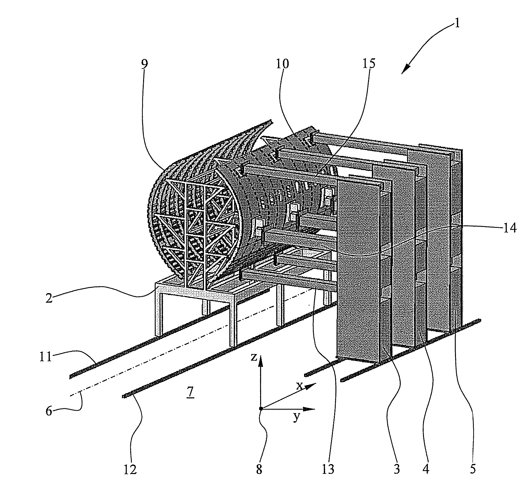
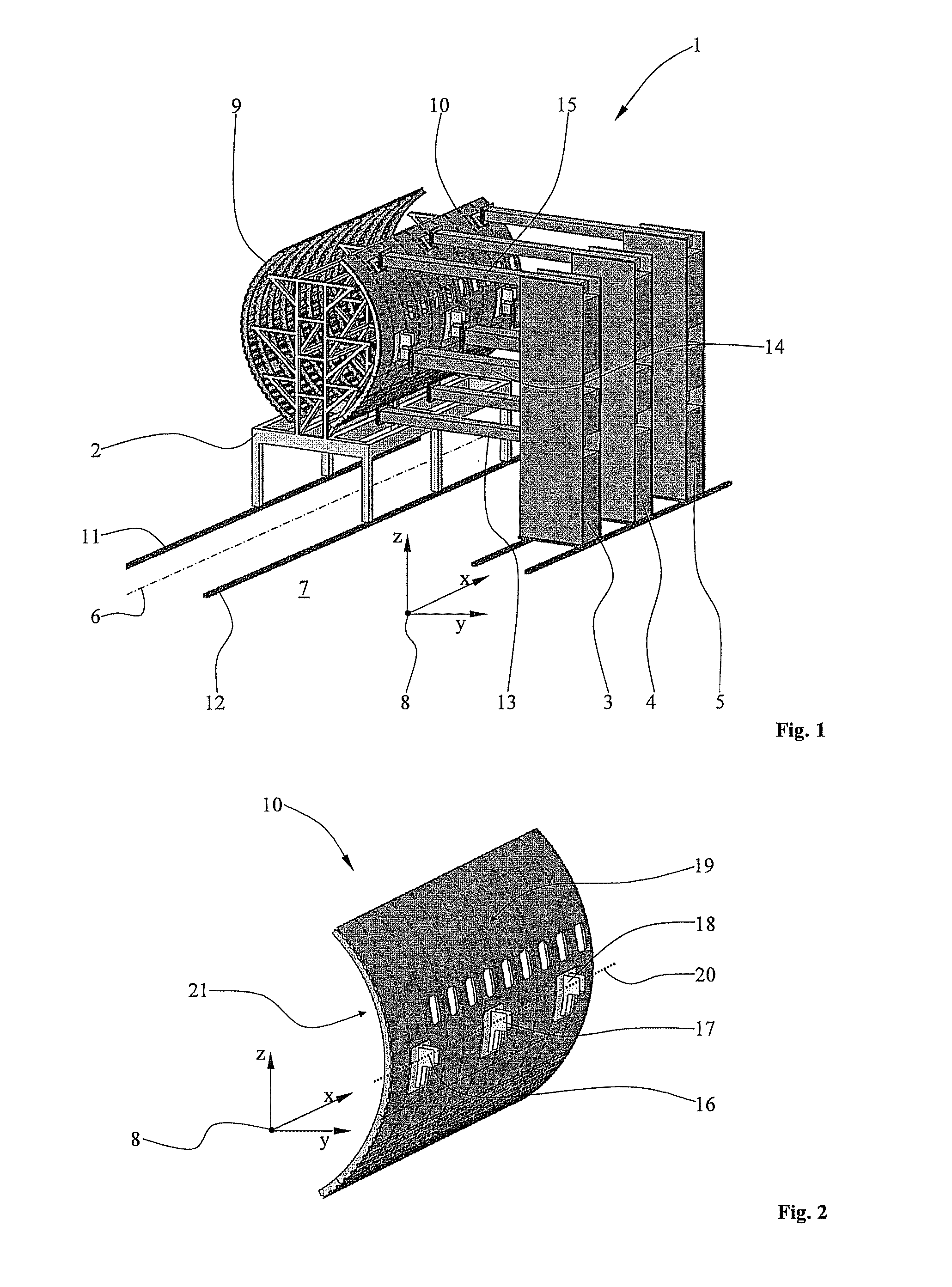
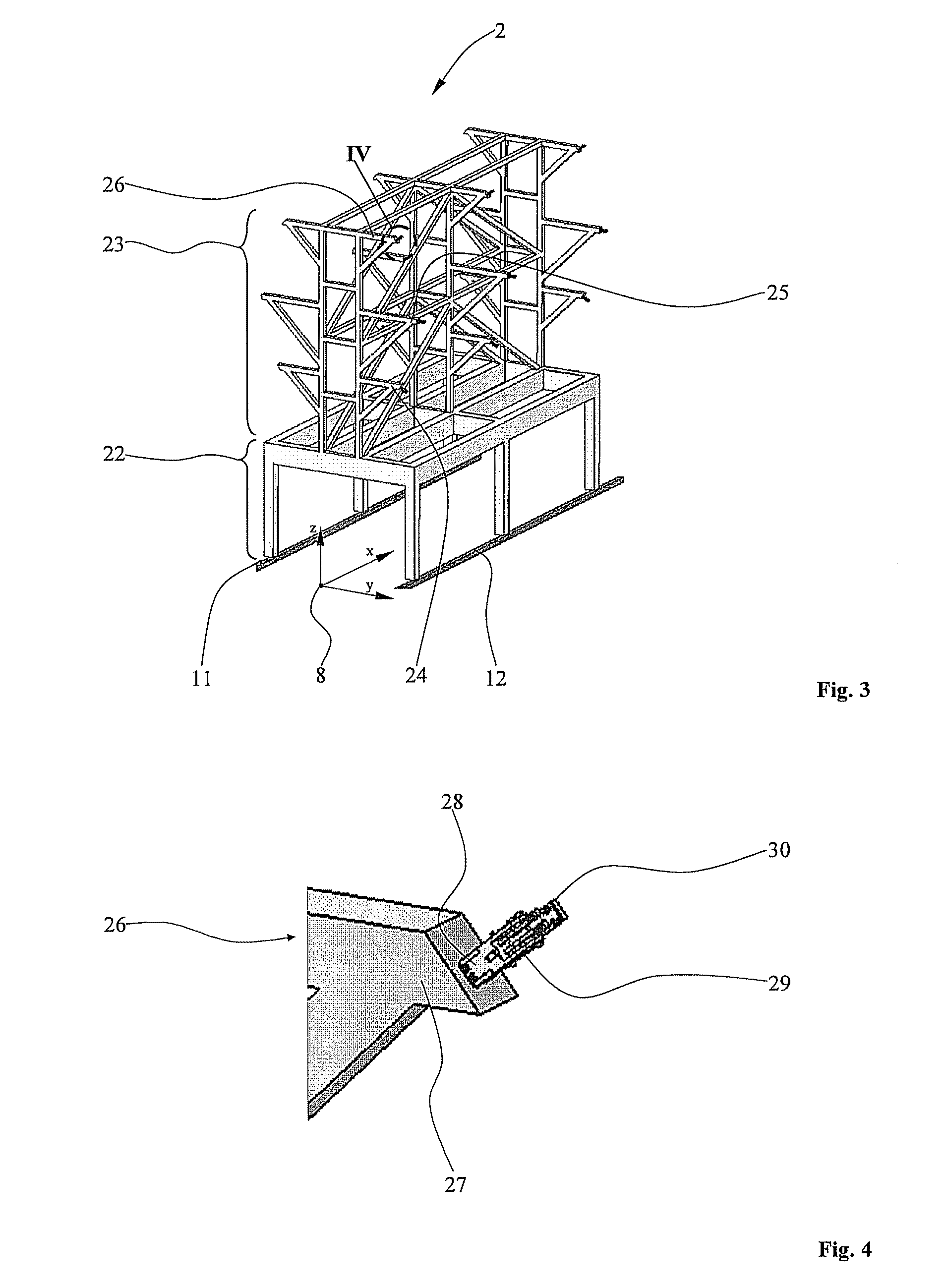
[0034]FIG. 1 is a perspective view of a right-hand part of a device. A device 1 comprises, inter alia, a side shell support 2 and three positioning towers 3 to 5 which are arranged on the right-hand side of a central line 6 in an assembly zone 7. A coordinate system 8 illustrates the spatial position of the components. In accordance with the positioning towers 3 to 5, the same number of positioning towers is arranged symmetrically to the central line 6, but these towers are not shown for reasons of clarity. Two side shells 9, 10 are received on the side shell support 2 and are provided for production of a fuselage portion (not shown) so as to create an aircraft fuselage cell. The side shell support 2 and the positioning towers 3 to 5 can be moved and positioned on rails, of which only two rails 11, 12 are provided with a reference numeral, in order to displaceably mount the side shell support 2 ...


PUM


Abstract

The invention relates to a device for the preferably automated supply of structural components to an assembly zone for producing a fuselage portion of an aircraft by multi-shell construction, comprising:a) at least one side shell support for introducing at least one side shell,b) at least two positioning towers for moving and aligning at least one side shell inside the device.The device according to the invention enables side shells to be quickly and precisely supplied to an assembly zone for production of an entire fuselage portion. It is possible to dispense completely with the hitherto required manual and therefore time-consuming “hovering” of side shells and other large structural components, such as upper shells, lower shells, floor frames and other technical equipment systems necessary for the production of a fuselage portion, this process being prone to problems and difficult to control.

Description

CROSS-REFERENCE TO RELATED APPLICATIONS[0001]This application claims the benefit of U.S. Provisional Application No. 61 / 119,234, filed Dec. 2, 2008, the entire disclosure of which is herein incorporated by reference.FIELD OF THE INVENTION[0002]The invention relates to a device for the preferably automated supply of structural components, in particular of at least two side shells, to an assembly zone for production of a fuselage portion of an aircraft by multi-shell construction.[0003]In modern aircraft construction, what is known as sectional construction is becoming increasingly common. A plurality of fuselage portions is assembled behind one another in order to form the finished aircraft fuselage cell. The fuselage portions themselves are usually produced by multi-shell construction, irrespective of whether composite materials or conventional aluminium construction is used. For example, two side shells together with an upper shell and a lower shell as well as at least one floor fr...

Claims


Application Information

Patent Timeline
IPC IPC(8): B65G49/00
CPCY10T29/49829B64F5/0009B64F5/10
Inventor WEBER, FRANK
Owner AIRBUS OPERATIONS GMBH
Learn More