Ultrasonic imaging apparatus and control method for ultrasonic imaging apparatus

a control method and ultrasonic imaging technology, applied in tomography, applications, instruments, etc., can solve the problems of difficult evaluation of valve functions, complicated operation, and parts to be diagnosed that cannot be clearly extracted from ultrasonic images, and achieve the effect of easy generation

Inactive Publication Date: 2010-06-03
KK TOSHIBA +1
View PDF19 Cites 9 Cited by
  • Summary
  • Abstract
  • Description
  • Claims
  • Application Information

AI Technical Summary

Benefits of technology

[0013]The above-mentioned embodiment is configured to generate an ultrasonic cross-sectional image by using received signals and relatively low-amplitude signals among those processed by the filtering process at each point on the scan line. Herein, the blurred virtual image of a valve in the filtering-processed data has larger amplitude than the other parts (high brightness, strong signal). Therefore, in the abovementioned composition, data on the blurred virtual image of a valve in the filtering-processed data is not used and the part is not displayed in the current cross-sectional image data. Accordingly, in the abovementioned composition, it is possible to remove the blurred virtual image of a valve from the ultrasonic cross-sectional image. By doing this, physicians do not have to turn the filtering process On and Off depending on the purpose of a diagnosis. In addition, it allows for easily generating an ultrasonic cross-sectional image in which the fixed artifacts are removed and that is appropriate for the evaluation of valve functions.

Problems solved by technology

Accordingly, there has been a defect in that the parts to be diagnosed are not clearly extracted from the ultrasonic image.
When using an image that contains a blurred virtual image of a valve for diagnostic imaging, it may disadvantageously make the evaluation of valve functions difficult.
Accordingly, there has been a problem in that it is necessary to switch the filter On and Off depending on the purpose of the diagnosis, complicating the operation; for example, the operator, such as a physician or an operation technician, turns the filter On for evaluations of the cardiac muscles and turns the filter Off for evaluations of valve functions.

Method used


Image

  • Ultrasonic imaging apparatus and control method for ultrasonic imaging apparatus
  • Ultrasonic imaging apparatus and control method for ultrasonic imaging apparatus
  • Ultrasonic imaging apparatus and control method for ultrasonic imaging apparatus

Examples


first embodiment

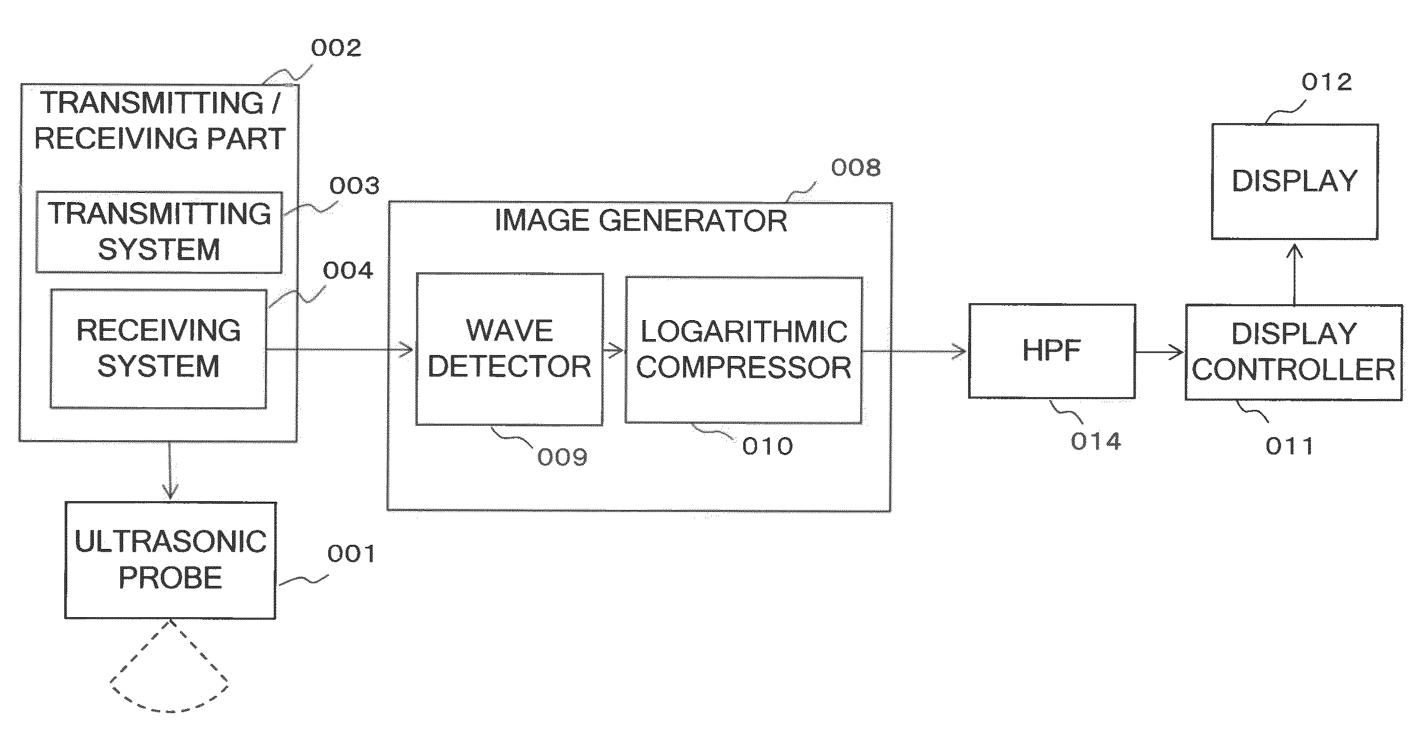
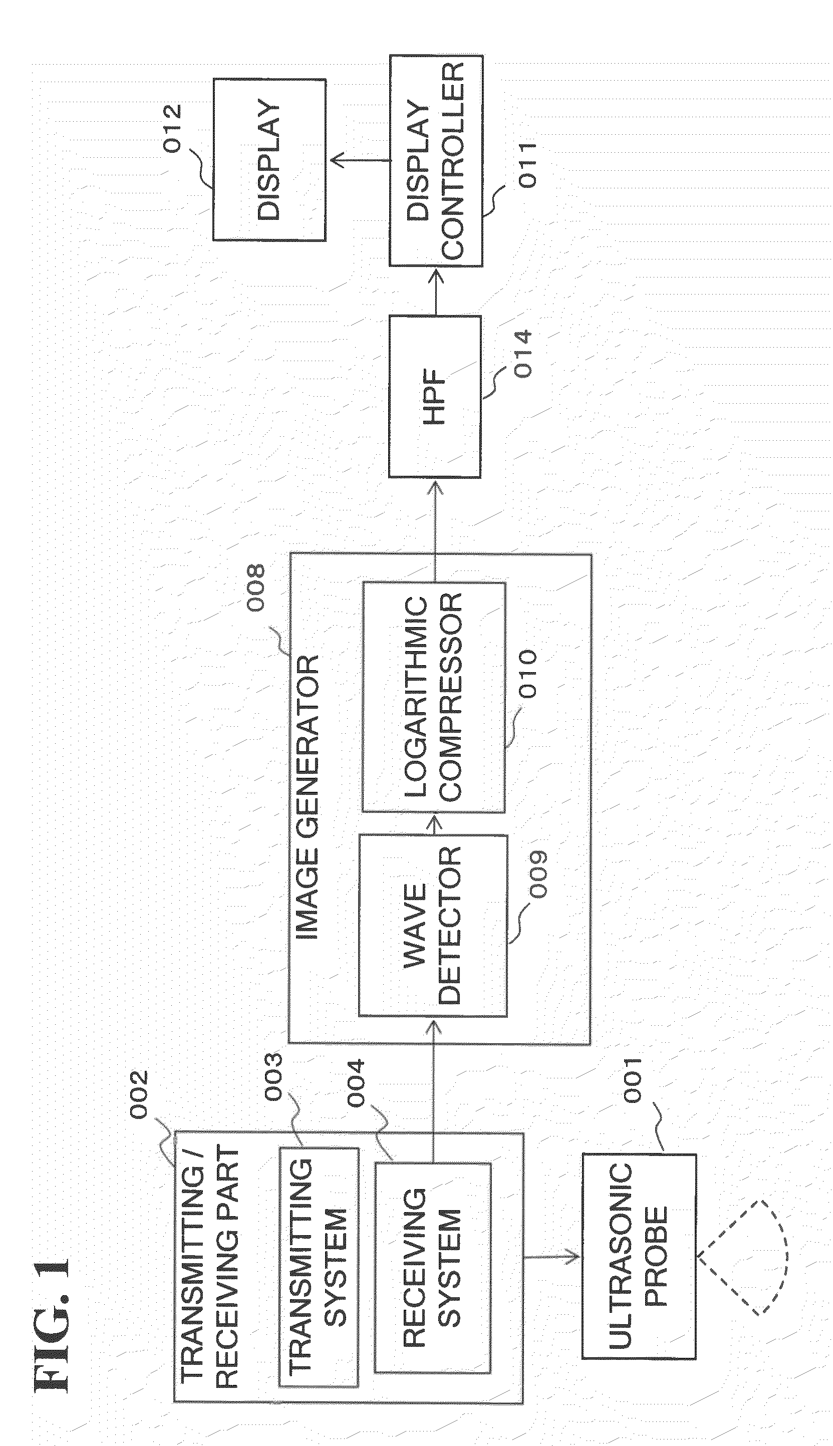
[0020]An ultrasonic imaging apparatus according to the first embodiment of the present invention will now be described. FIG. 2 is a block diagram showing the functions of an ultrasonic imaging apparatus according to the present embodiment. Herein, the embodiment is described as one that employs a sector electronic scan mode as the scan mode, but it may be a linear electronic scan mode or a convex scan mode.

[0021]On the tip of the ultrasonic probe 001, a plurality of piezoelectric elements that reversibly convert mechanical vibrations and electrical signals are arranged and mounted in one dimension. For each piezoelectric element, a single channel is assigned for scanning a cross section of the subject. This may be a composition in which a plurality of adjacent piezoelectric elements is equivalent to a single channel. The ultrasonic probe 001 is connected to a transmission system 003 of a transmitting / receiving part 002 (described below) during transmission and connected to the recei...

second embodiment

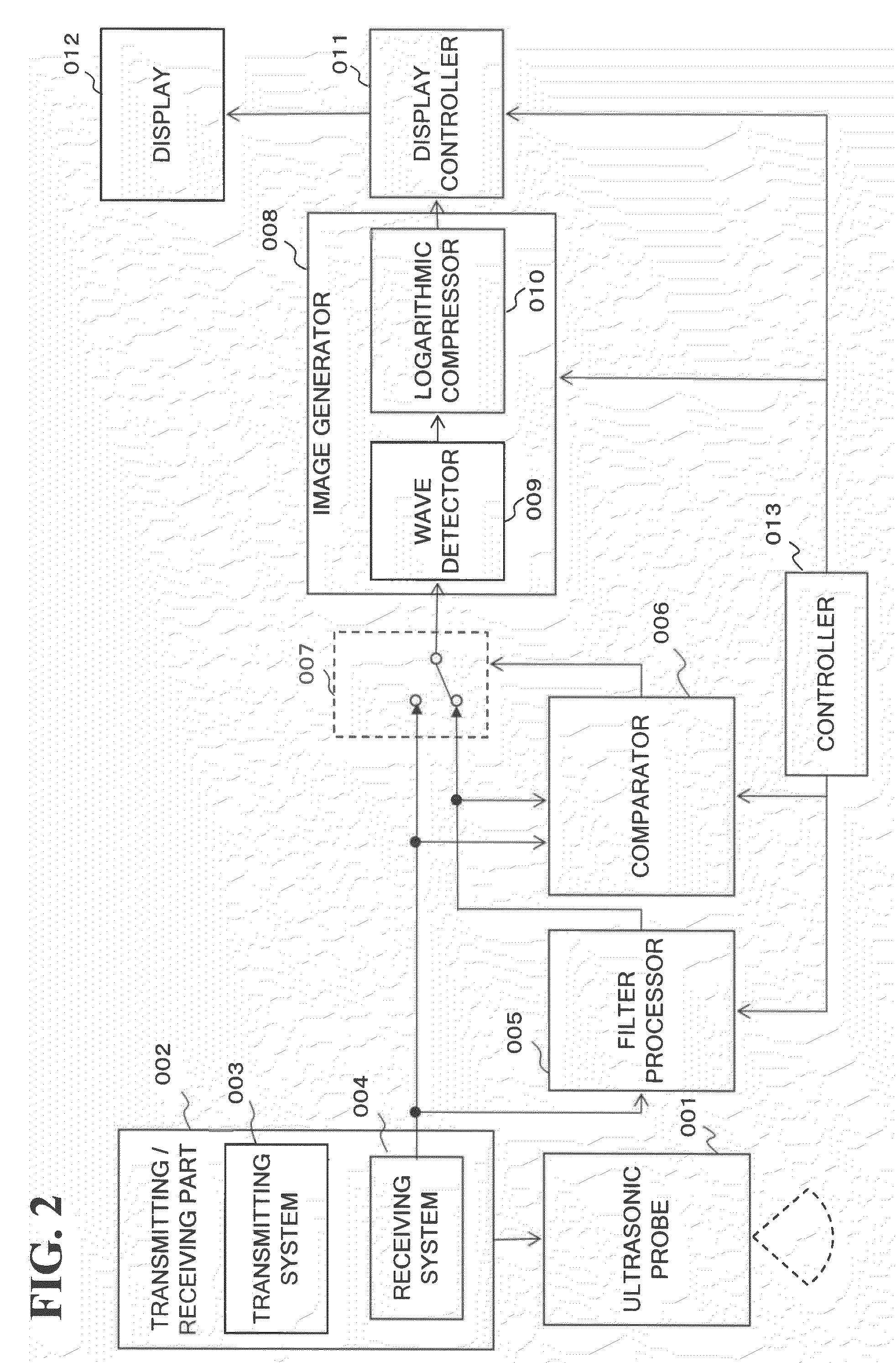
[0058]Next, an ultrasonic imaging apparatus according to the second embodiment of the present invention will be described. The ultrasonic imaging apparatus according to the present embodiment is different from the first embodiment in that the filtering process and comparison of digital signals are performed after wave detection. Therefore, the following description will mainly describe signal processing from the receiving system to the switch. In the following description, unless specified otherwise, functioning parts with identical numbers with the first embodiment have the same functions. FIG. 6 is a block diagram showing the functions of the ultrasonic imaging apparatus according to the present embodiment.

[0059]The wave detector 009 receives an input of the digital signal xi in the current frame from the receiving system 004. The wave detector 009 detects the wave amplitude of the received signal. This extracts amplitude information. For the wave detector 009, as the received sig...


PUM


Abstract

A scanning part ultrasonically scans a cross section of a subject corresponding to a frame period. The filter processor uses time-series received signals that are obtained from the scanning part corresponding to a plurality of frames to attenuate low-frequency components from the received signals of a plurality of locations within the cross section. The amplitude-comparator compares the amplitudes of the received signals with the amplitudes of the signals for which the low-frequency components have been attenuated, and the signals with smaller amplitudes are output. The image-generator generates morphological images of the subject based on the output signals from the amplitude-comparator.

Description

BACKGROUND OF THE INVENTION[0001]1. Field of the Invention[0002]The present invention relates to: an ultrasonic imaging apparatus that generates ultrasonic cross-sectional images based on at least either phase information or amplitude information included in a received signal obtained by ultrasonically scanning a cross section of a subject; and a control method for an ultrasonic imaging apparatus.[0003]2. Description of the Related Art[0004]Generating a cross-sectional image that shows tissue distribution (i.e., a B mode image) requires two nonlinear processes comprising amplitude wave detection and logarithmic compression of the received signals. Ultrasound radiated within the subject is reflected at the border of acoustic impedance. The reflection intensity is proportional to the difference in the acoustic impedance. When the transmitted ultrasound is considered as a carrier wave, the reflection phenomenon is equivalent to amplitude modulation. Accordingly, by performing wave dete...

Claims


Application Information

Patent Timeline
Patent Type & Authority Applications(United States)
IPC IPC(8): A61B8/14
CPCA61B8/14G01S15/8981G01S7/52087G01S7/52077
Inventor KAKEE, AKIHIRO
Owner KK TOSHIBA
Why Eureka
Try Eureka