
Storage management server and storage configuration relocating method

a storage management server and storage configuration technology, applied in the direction of electrical apparatus construction details, liquid/fluent solid measurements, instruments, etc., can solve the problems of reducing cooling efficiency, ignoring the amount of heat generated, and increasing the amount of energy consumed by the entirety of the storage system, so as to increase the storage capacity per storage device, increase the amount of energy, and increase the amount of data

Active Publication Date: 2010-06-03
HITACHI LTD
View PDF23 Cites 14 Cited by
  • Summary
  • Abstract
  • Description
  • Claims
  • Application Information

AI Technical Summary

Benefits of technology

[0006]Recent advances in information technology (IT) infrastructures result in a rapid increase in amount of data to be stored. In this technical background, data-saving storage systems expand in scale and, simultaneously, physical devices are becoming higher in integration in order to increase the storage capacity per storage device, which leads to a noticeable increase in amount of an energy to be consumed by an entirety of the storage system. A currently developed approach to coping with such circumstances and minimizing energy consumption of the entire storage system is to design the system to have a built-in control mechanism for temporarily halting those physical devices with no input / output sessions being occurred with respect to the stored data thereof.
[0007]Unfortunately, the approach fails to take into consideration the amount of heat to be generated by the storage system per se. Prior known systems are designed to use a cooling device, which is merely rendered operative without recognizing temperatures and positions of presently operating physical devices. Accordingly, this system design suffers from decreased cooling efficiency in such the operation environment, and thus is encountered with a problem as to the incapability of minimizing the amount of an energy to be consumed for the device cooling purpose.
[0014]With this arrangement, it becomes possible for a storage system administrator to recognize a present operation environment, including physical positions of data-storing physical devices and temperatures of physical devices. It is also possible for the administrator to recognize the position and influenceability of a variable factor generation source(s) with respect to physical devices. Additionally, comparing present operating states of physical devices to the operation environment threshold value makes it possible to achieve the intended storage configuration relocation for optimizing physical device operation environments. This makes it possible to minimize storage system operations / maintenance costs, including the storage system's environment sustenance cost as will be described in detail later.

Problems solved by technology

In this technical background, data-saving storage systems expand in scale and, simultaneously, physical devices are becoming higher in integration in order to increase the storage capacity per storage device, which leads to a noticeable increase in amount of an energy to be consumed by an entirety of the storage system.
Unfortunately, the approach fails to take into consideration the amount of heat to be generated by the storage system per se.
Accordingly, this system design suffers from decreased cooling efficiency in such the operation environment, and thus is encountered with a problem as to the incapability of minimizing the amount of an energy to be consumed for the device cooling purpose.
Another problem faced with the prior known storage system is the risk that relocation of storage configuration with respect to a presently operating physical device(s) can result in local deterioration of the operation environment of a storage configuration after the relocation.
This results in a decrease in reliability of the storage system per se and also in an increase in system maintenance costs.

Method used


Image

  • Storage management server and storage configuration relocating method
  • Storage management server and storage configuration relocating method
  • Storage management server and storage configuration relocating method

Examples


Embodiment Construction

[0038]A currently preferred form (referred to hereinafter as embodiment) for implementation of this invention will be described with reference to the accompanying drawings below.

(System Configuration)

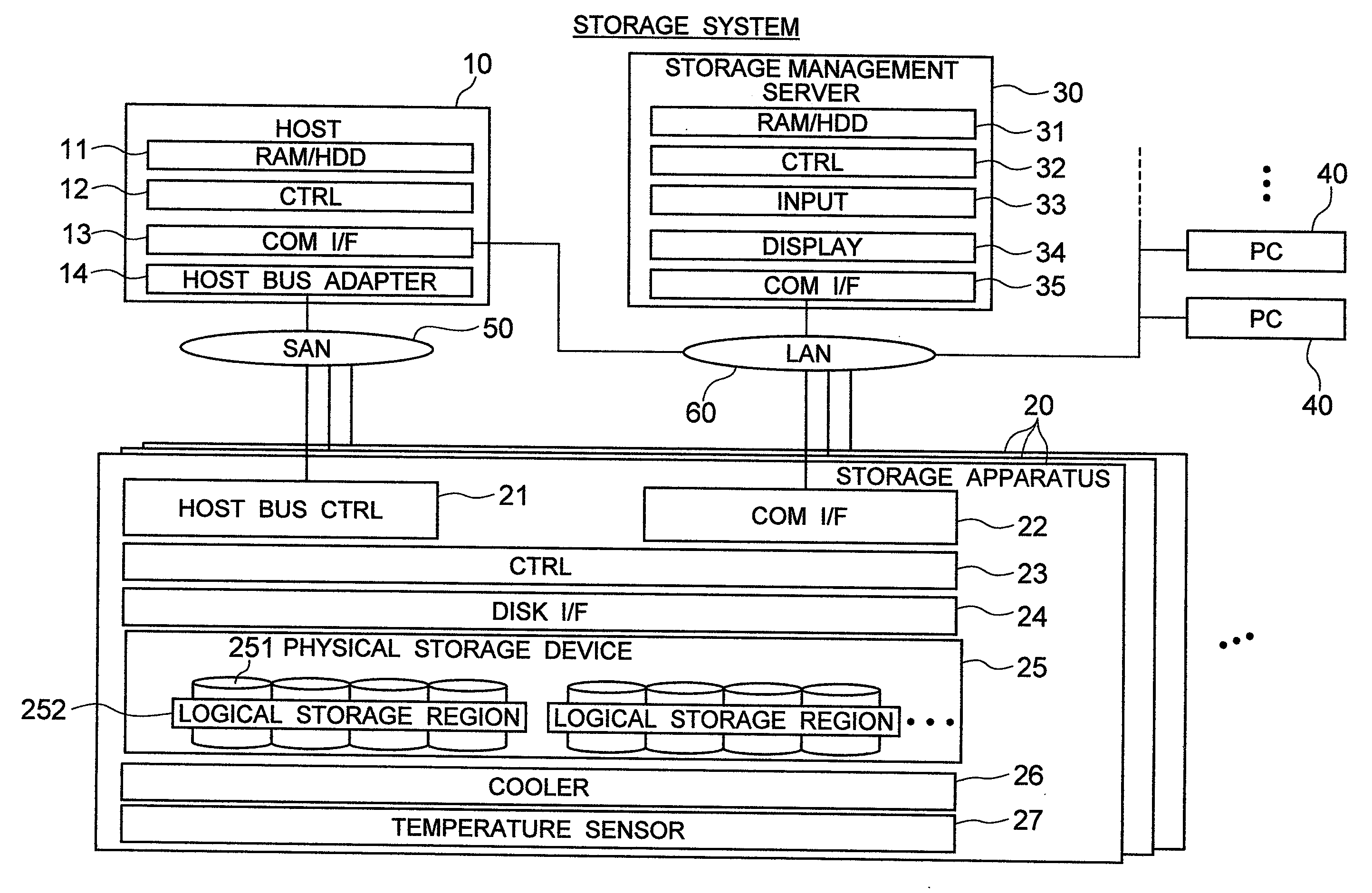
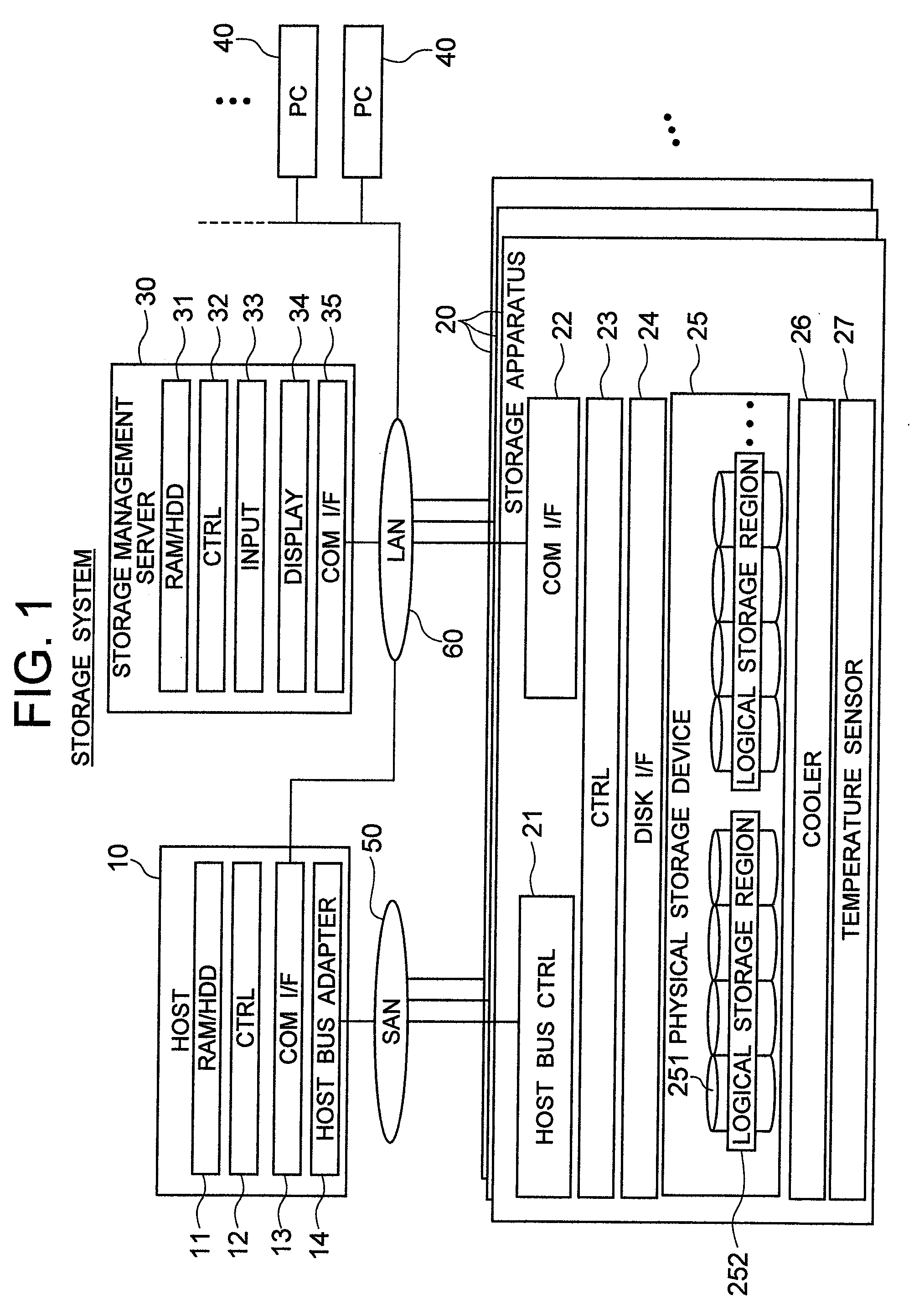
[0039]FIG. 1 shows an overall configuration of a storage system in accordance with one embodiment of this invention. This storage system is generally made up of a host computer 10, a plurality of storage apparatuses 20, a storage management server 30 and two or more user computers 40. The host 10 and storage apparatuses 20 are communicably coupled together via a storage area network (SAN) 50. The host 10, storages 20, server 30 and computers 40 are communicably interconnected via a local area network (LAN) 60.

[0040]The host 10 may typically be a file server, which includes several hardware components, such as a storage unit 11, control unit 12, communication interface (I / F) 13, and host bus adapter 14.

[0041]The host's storage 11 is for storing therein software programs for executing pre...


PUM


Abstract

A storage management server collects, stores and displays positions, temperatures and temperature threshold values of physical storage devices from a storage apparatus. It collects, stores and displays positions and power consumptions of variable factor generation sources which are factors that cause the physical storage devices to vary in operation environments, and also calculates the influenceability by variable factor generation sources against the physical storage devices and affected temperatures thereof. It compares the temperature of a given physical storage device to a temperature threshold value of this physical storage device or compares it to an affected temperature thereof due to the variable factor generation sources, thereby moving, for data transfer, an operation position of physical storage device based on a comparison result at such time.

Description

INCORPORATION BY REFERENCE[0001]The present application claims priority from Japanese application JP2008-305598 filed on Nov. 28, 2008, the content of which is hereby incorporated by reference.BACKGROUND OF THE INVENTION[0002]This invention relates to operation environment-dependent storage relocation realizing technologies.[0003]A storage system is generally arranged to have at least one storage apparatus, such as a disk array subsystem or like equipment. This storage apparatus includes physical devices such as hard disk drives (HDDs) and / or semiconductor memory drives or else, which are disposed in an array form for providing storage regions based on a redundant array of independent (inexpensive) disks-i.e., RAID. The storage system also includes a host computer (referred to as the “host” hereinafter), which gives access to the storage regions provided by the storage apparatus to thereby perform data read / write operations. The storage system further includes a storage management s...

Claims


Application Information

Patent Timeline
Patent Type & Authority Applications(United States)
IPC IPC(8): G06F1/26G06F12/00
CPCG06F1/206G06F1/3203Y02B60/1275H05K7/20836G06F11/324Y02D10/00
Inventor OBANA, MANABUTAKAYAMA, YOSHIHITO
Owner HITACHI LTD
Learn More