Hand held sign

Inactive Publication Date: 2010-06-10
COUTU RAYMOND
5 Cites 2 Cited by

AI-Extracted Technical Summary

Problems solved by technology

However, security concerns have arisen that the sticks or dowels could be used as weapons during the event and for this...

Benefits of technology

[0007]Advantageously, the present invention provides a sign which is attractive and useful in displaying the desired information or message and which is easy to manufacture and which sign does not utilize a stick or dowel for the support thereof, thereby eliminating or reducing security concerns associated with sticks or dowels b...

Abstract

A hand held sign comprising, a support medium adapted to display a message, text, image or other indicia and having two holes in spaced relationship to one another therein and a handle to support the support medium wherein the handle is formed by that support medium material that remains between the two holes.

Application Domain

Mobile visual advertisingShow cards

Technology Topic

Electrical and Electronics engineeringHand held

Image

  • Hand held sign
  • Hand held sign
  • Hand held sign

Examples

  • Experimental program(1)

Example

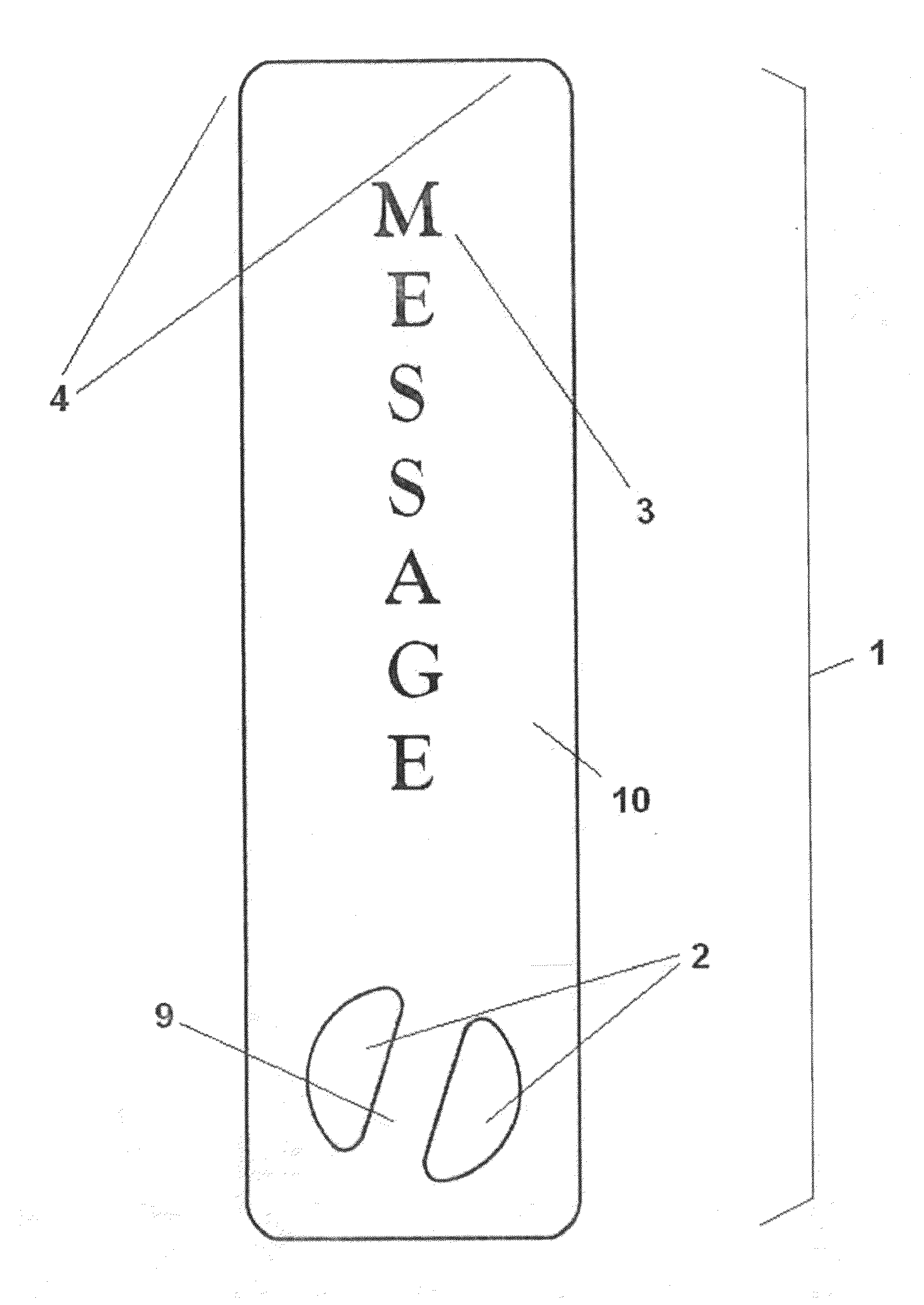
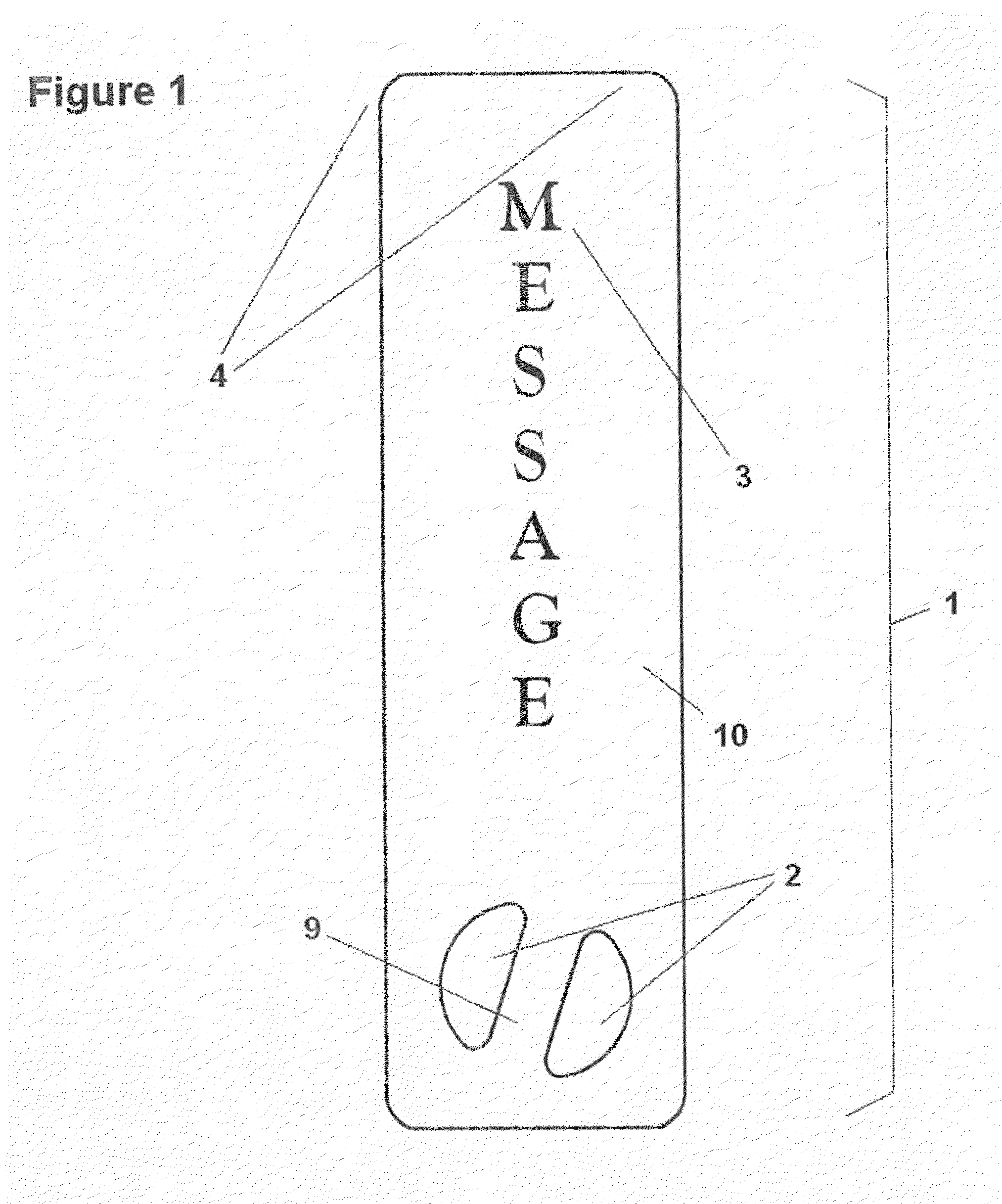
[0012]With reference to FIGS. 1 and 3, a sign generally identified by reference numeral 1 is provided. In a preferred embodiment, a support medium 10 of size, shape and orientation suited to the event and message to be displayed is provided (it being understood that a wide variety of shapes, sizes and orientations may be the subject matter of the present invention, including, for example squares, rectangles, circles, ovals and other fanciful shapes, and vertical, horizontal or diagonal orientations as would be understood by a person skilled in the art).
[0013]In the embodiment illustrated in FIGS. 1 and 3 a generally rounded rectangular design is provided, the rounded corners 4 of the design of this embodiment providing additional safety characteristics for the sign, eliminating sharp corners associated with the 90 degree angles on the corners of a rectangle.
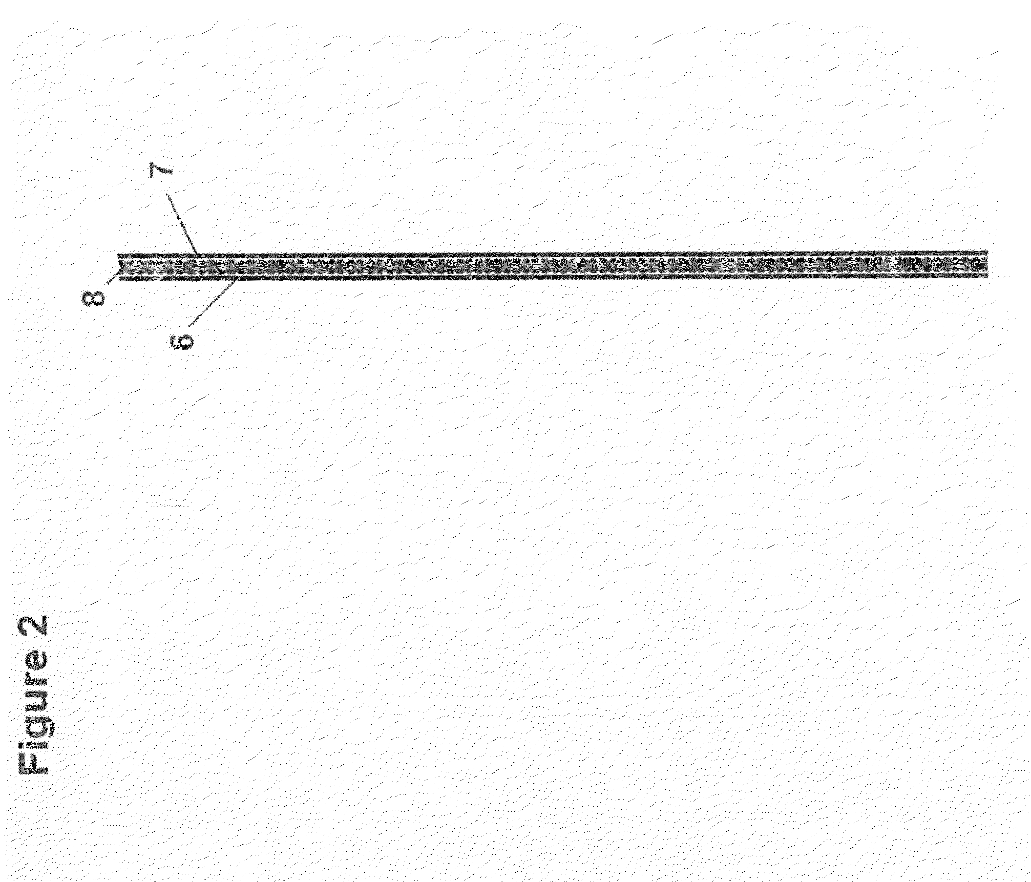
[0014]In the preferred embodiment, the support medium 10 is made of a thin sheet of corrugated cardboard, it being understood that a wide variety of different materials may alternatively be utilized, including, for example thick paper, non-corrugated cardboard, plastic sheeting or corrugated plastic, and other materials known to a person skilled in the art. The front surface of the support medium may be used to display a message 3 or other text, image or indicia, generally shown as the word MESSAGE 3. Similarly, as illustrated in FIG. 3, the rear surface of the support media may be used to display the same, or an alternative message or other text, image or indicia, generally shown as the word ALTERNATIVE 5 in FIG. 3. The message text, image or other indicia may be printed, affixed or otherwise displayed on the surfaces of the support media in a manner known to a person skilled in the art. In an alternative embodiment, thick card stock paper (or any other printing substrate as would be known to a person skilled in the art) may utilized in the context of the present invention, the text, image or indicia being printed on the card stock or other substrate and thereafter applied to the support medium by gluing, lamination or such other manner as would be known to a person skilled in the art. This embodiment also provides an additional functional characteristic as it provides additional stiffness and strength.
[0015]As illustrated in the cross-sectional view of FIG. 2, in the preferred embodiment of the present invention, the support media may be corrugated cardboard, having a forward facing surface 6 and rearward facing surface 7, and sandwiched there-between a thin layer of corrugating cardboard material 8 which has been glued or otherwise securely attached to both the forward facing surface 6 and rear ward facing surface 7 to provide a rigid or semi-rigid support medium in a manner known to person skilled in the art. In alternative embodiments of the present invention, alternative structures may be used in respect of the support medium as would be understood by a person skilled in the art.
[0016]In the preferred embodiment of the present invention, as illustrated in FIGS. 1 and 3, there is provided, as an integral part of the support medium, a handle 9 formed by two generally half-moon shaped 2 holes provided in the support medium, the handle 9 in the preferred embodiment being positioned and angled from the vertical so as to provide an ergonomically suitable grip and angle from the vertical to allow for a comfortable, yet solid grip. In the preferred embodiment, the half-moon shaped 2 holes are slightly larger than the size required to permit a gloved human hand to pass easily therethrough it being understood that the size of these holes may vary and be adapted for the use of the users as would be understood by a person skilled in the art. In the preferred embodiment, the handle is angled at between 10 and 20 degrees from the vertical, and preferably at approximately 17 degrees from the vertical, it being understood that a wide range of angles may alternatively be selected to suit the preferences of the users of the signs. As the sign's messages or images may be printed or otherwise affixed to either side of the sign, the sign may readily be reversed, thereby reversing the orientation of the handle relative to the displayed message, to permit the sign to be readily used by left handed and right handed users. It is also understood that in alternative embodiments of the present invention, the holes 2 may be square, rectangular or such other shape as would be understood by a person skilled in the art. In the preferred embodiment, the handle 9 is positioned in the lower part of the support medium, it being understood that in alternative embodiments, the handle 9 may be positioned elsewhere on the support medium, such as, for example, in the middle or upper parts of the support medium.
[0017]To use the sign of the present invention, one or more messages, images or other indicia is printed, affixed or otherwise displayed one or both surfaces of the support media in a manner known to a person skilled in the art, and at the event for which the sign is being utilized, the user, in the case of the preferred embodiment, inserts the fingers of one hand into one of the holes 2 and inserts the thumb in the other, thereby positioning the handle 9 of the sign in the palm of the user's hand where it can be readily and securely grasped and manipulated by the user.
[0018]The present invention has been described herein with regard to preferred embodiments. However, it will be obvious to persons skilled in the art that a number of variations and modifications can be made without departing from the scope of the invention as described herein.

PUM

no PUM

Description & Claims & Application Information

We can also present the details of the Description, Claims and Application information to help users get a comprehensive understanding of the technical details of the patent, such as background art, summary of invention, brief description of drawings, description of embodiments, and other original content. On the other hand, users can also determine the specific scope of protection of the technology through the list of claims; as well as understand the changes in the life cycle of the technology with the presentation of the patent timeline. Login to view more.

Similar technology patents

Electronic component mounted structure and method of manufacturing the same

InactiveUS20090246474A1good connection reliabilityeasily manufacture
Owner:PANASONIC CORP

Classification and recommendation of technical efficacy words

  • easily manufacture

Dispensing system

ActiveUS20070278164A1easily manufactureprevent theft
Owner:WESTROCK SHARED SERVICES LLC

Reciprocating compressor and manufacturing method thereof

InactiveUS20060024181A1easily manufactureprevent abrasion
Owner:LG ELECTRONICS INC
Why Eureka
Try Eureka