Method for mounting in sections an annular tower for wind power generator, heliostatic power generator or chimney composed from three concrete segments or more

a technology of prestressed concrete and wind power generators, applied in the direction of building components, structural elements, building scaffolds, etc., can solve the problems of difficult handling, large and heavy sections, and limited heigh

Inactive Publication Date: 2010-06-10
CORTINA INNOVATIONS DE C V
View PDF21 Cites 55 Cited by
  • Summary
  • Abstract
  • Description
  • Claims
  • Application Information

AI Technical Summary

Benefits of technology

[0026](e) to install, with a crane of medium or low capacity, the concrete segments to conform the concrete tower section, firmly join the concrete segments through pre-stressing tendons;

Problems solved by technology

In both cases, their height is limited because of their dimensions, the turbulence caused by the air, their strength against intense earthquakes, and their ease of building, because in many cases it is not practical for the heights presently used.
The main drawback of the ENERCON tower is that the sections are big and heavy and so that, difficult to handle.
For mounting them it requires of expensive high capacity cranes.
The mounting method has many drawbacks, for example, the tower requires very complex joints for joining the segments—see FIGS. 13a to 13d of patent WO-2003069099-.
It should be noted that segments of 12 meters height and some tons weight can be easily assembled at the floor level; however at 30 meters height it is not easy to joint the segments with the required precision.
In addition, the MECAL joint must be cemented which makes the erection more complex.
Furthermore, the segments are made using different molds and it is probable that the segments cannot coincide.
Moreover, presstressing in the inner side of the tower—as suggested by MECAL—is non recommendable since it produces weakness in the tower.
Bolt connections for joining the concrete segments are also non recommendable since any movement of the tower—an earthquake, for instances—produce movement in the tower segments that can destroy such bolts.
The use of such crane requires that the tower be over-designed in order to support its own weight as well as the weight of crane and it is difficult to handle at high levels—more than 30 meters—.
Because there are a number of different molds, the joining of the pieces is a difficult factor, requiring complex devices to accomplish such joining.
Because of their sizes, such segments are big and heavy.
With respect of the mounting methods of segmented concrete towers of the prior art, they share the following drawbacks:
a) In the case of ENERCON, CONCRETE & STEEL and INNEO towers, the erection of these sections must be done with large-capacity cranes, able to lift complete concrete tower sections. Mounting such concrete segments demands a considerable quantity of time and it is also difficult to keep the segments in an exact position to provide the required joints of the concrete segments. The mounting according to the prior art is also affected for the weather conditions, particularly the wind. Usually some time is lost by waiting the appropriate weather conditions for conducting the necessary mounting works. In addition, for mounting segments at high levels of height it is required to provide scaffolds for the working personnel as well as special security kits, which influences the cost of said erection.
b) In the case of MECAL, which uses a climbing crane, the concrete tower must be over dimensioned in order that the lower sections support the weight of the crane as well as the upper concrete segments. Furthermore, by the use of such method it is not possible to obtain the required precision joint of adjacent concrete segments.

Method used


Image

  • Method for mounting in sections an annular tower for wind power generator, heliostatic power generator or chimney composed from three concrete segments or more
  • Method for mounting in sections an annular tower for wind power generator, heliostatic power generator or chimney composed from three concrete segments or more
  • Method for mounting in sections an annular tower for wind power generator, heliostatic power generator or chimney composed from three concrete segments or more

Examples


Embodiment Construction

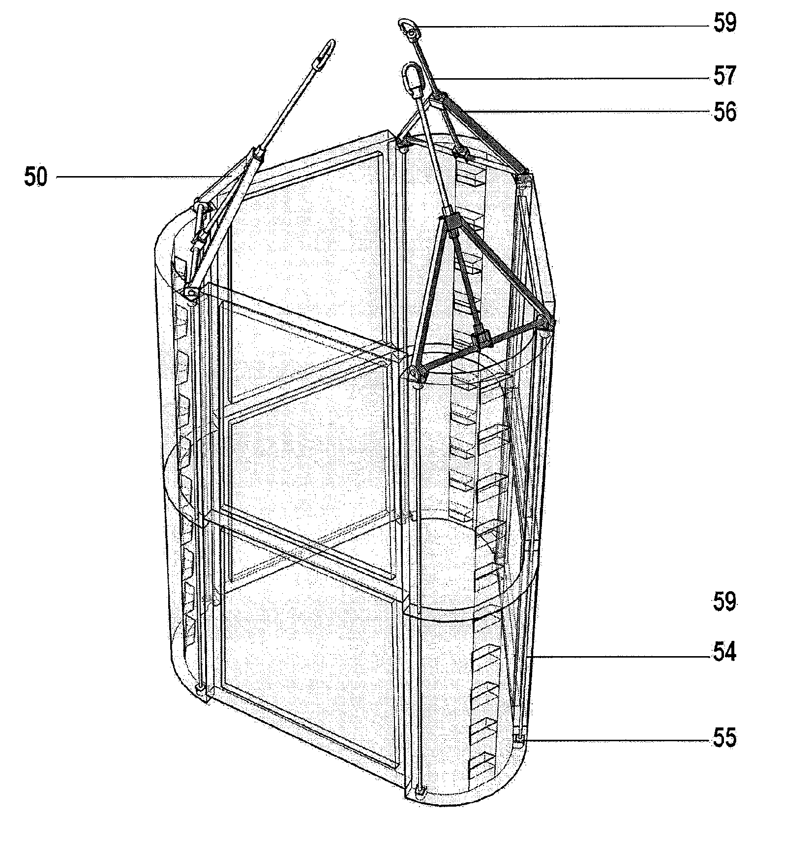
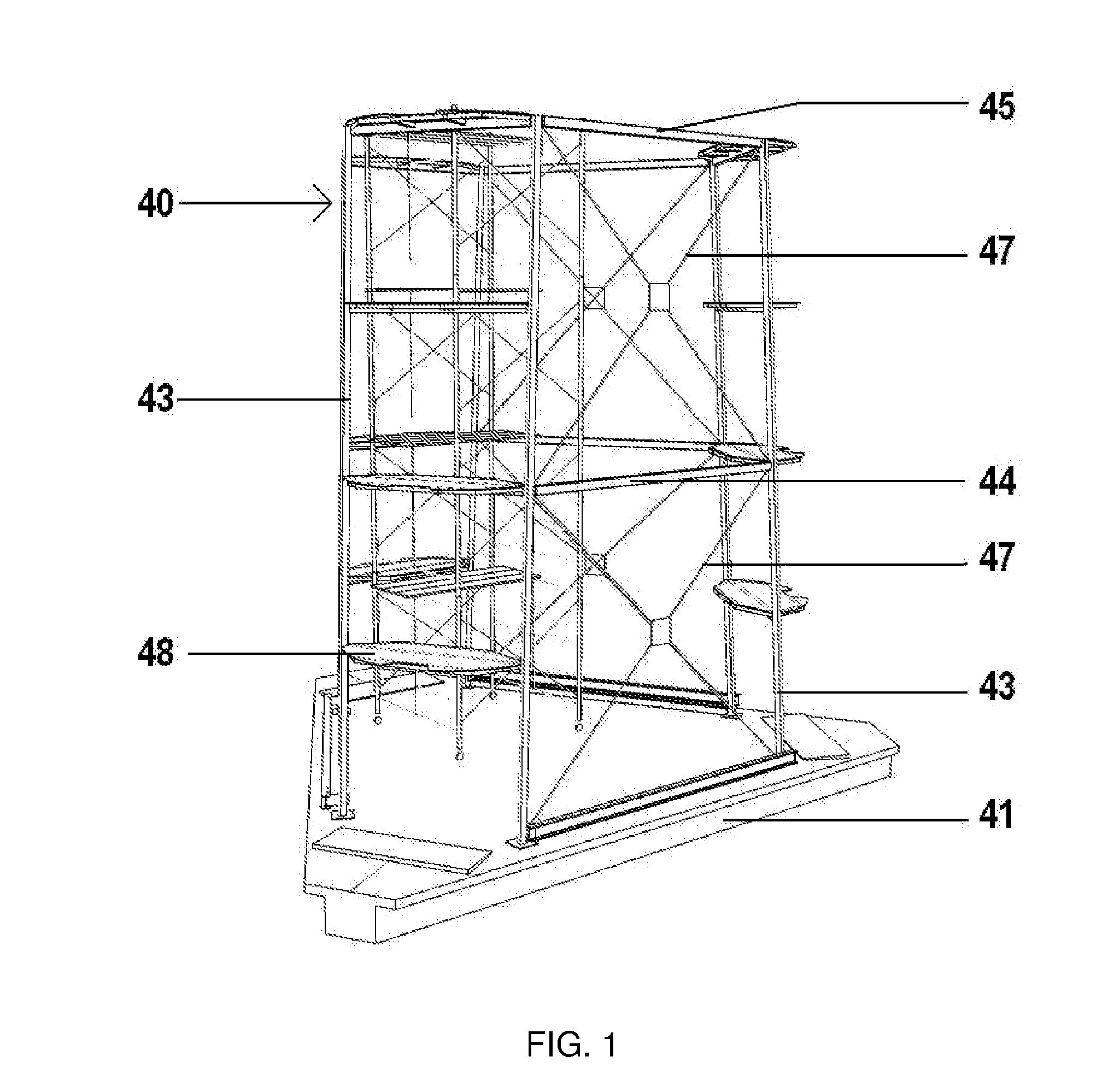
[0045]The tower, chimney or pole of the present invention is made of pre-stressed concrete, hereinafter only referred as tower, and it is tapered. The tower is an elongated structure having a cross-section decreasing as a function of the tower height. Accordingly, the diameter of the base is bigger than the diameter on the top. The tower is annular, that means that the tower comprises an external and internal surfaces and an inner gap. The tower can assume any geometry.

[0046]The present invention overcome every drawback of the prior art previously described.

[0047]The height of the tower is variable, and in the case of towers for wind or heliostatic generators, such height depends on the capacity of the nascelle or wind generator or solar receiver to be mounted on.

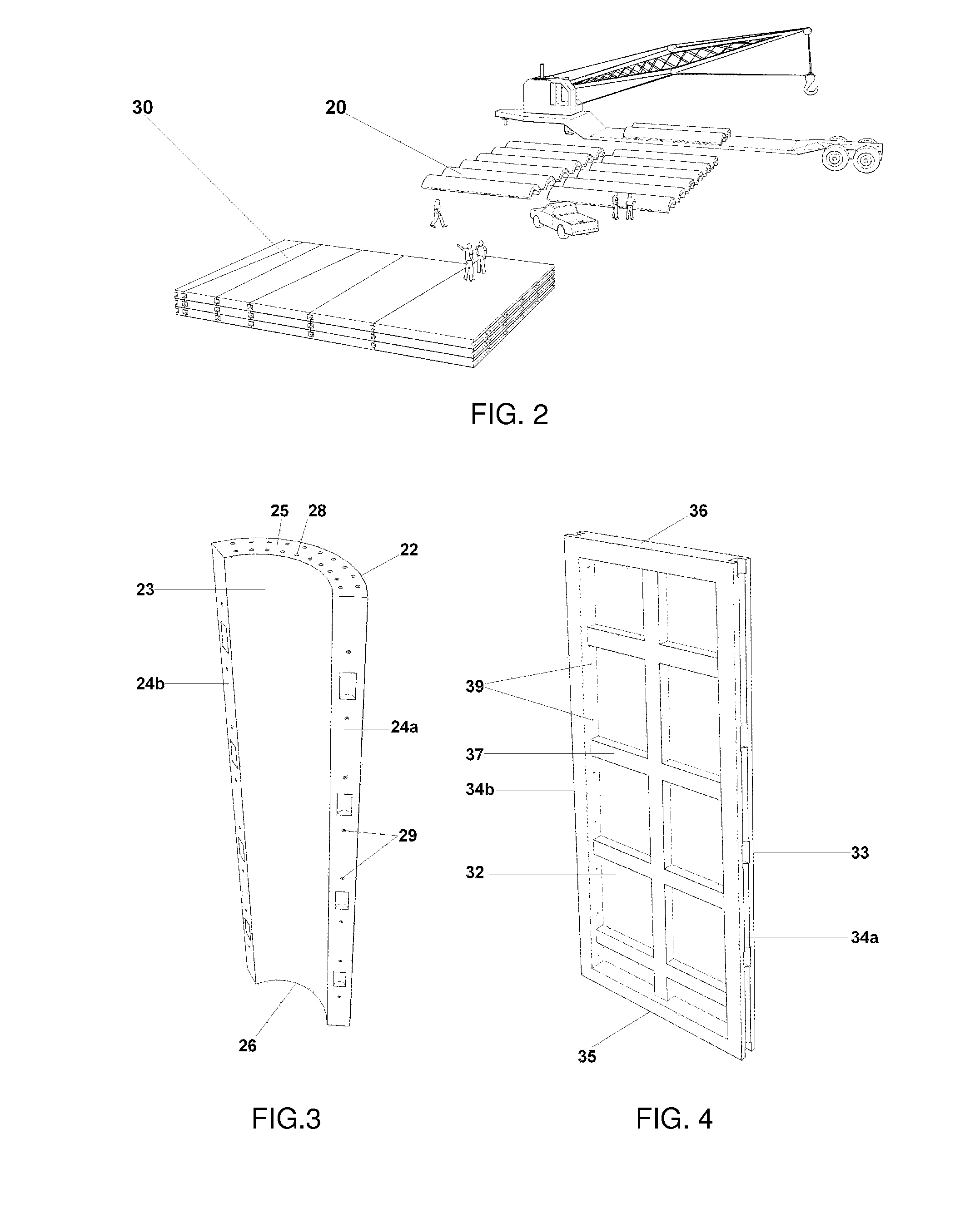
[0048]In an embodiment of the invention, the tower includes an elongated tapered structure formed of concrete legs and concrete joining walls. The concrete legs are formed from prefabricated concrete curved segments (herein...


PUM


Abstract

A method for erecting a pre-stressed sectionalized and segmented concrete tower for wind power or heliostatic generator or chimney comprising the steps of (a) building a tower foundation; (b) fabricating a plurality of concrete segments having internal ducts for introducing pre-stressing tendons; (c) fabricating a plurality of assembling supports and lifting harnesses for proving a support to the concrete segments when assembled in tower sections; (d) installing, with a crane the concrete segments to conform the concrete tower section; (e) engaging a lifting harness to the concrete tower section, lift the whole section of tower, mount such concrete section on the foundation and disengage the lifting harness and/or the assembling support; (f) assembling the following concrete tower sections though the use of assembling supports and mounting such tower sections through the use of lifting harnesses; and (g) joining the concrete sections through prestressing tendons to provide a rigid tower.

Description

CROSS-REFERENCE TO RELATED APPLICATIONS[0001]This non-provisional application claims priority under 35 U.S.C. §119(e) on U.S. Provisional Application No. 61 / 121,381, filed on Dec. 10, 2008, the entirety of which is incorporated herein by reference.BACKGROUND OF THE INVENTION[0002]1. Field of the Invention[0003]This invention relates to a method for mounting a segmented pre-stressed concrete tower for wind power generators and chimneys. Particularly, this application relates to a prestressed concrete tower for wind-power or heliostatic generators, particularly pre-stressed sectioned and segmented concrete tower for wind power or heliostatic generators, and its erecting method, as well as a tower section assembling support and a lifting harness for erecting the tower or chimney.[0004]2. Description of the Related Art[0005]Towers of several designs have been proposed for wind-power or heliostatic generators. For example, several different towers have been built, having structures based...

Claims


Application Information

Patent Timeline
Patent Type & Authority Applications(United States)
IPC IPC(8): E04G21/14E04H12/34E04C5/08E04G1/04
CPCE04H12/16E04H12/34E04H12/28E04H12/342
Inventor CORTINA-CORDERO, ALEJANDROCORTINA ORTEGA, JOSE PABLOCORTINA CORDERO, JOSE PABLO
Owner CORTINA INNOVATIONS DE C V
Why Eureka
Try Eureka