Harvester bucket
- Summary
- Abstract
- Description
- Claims
- Application Information
AI Technical Summary
Benefits of technology
Problems solved by technology
Method used
Image

Examples
first embodiment
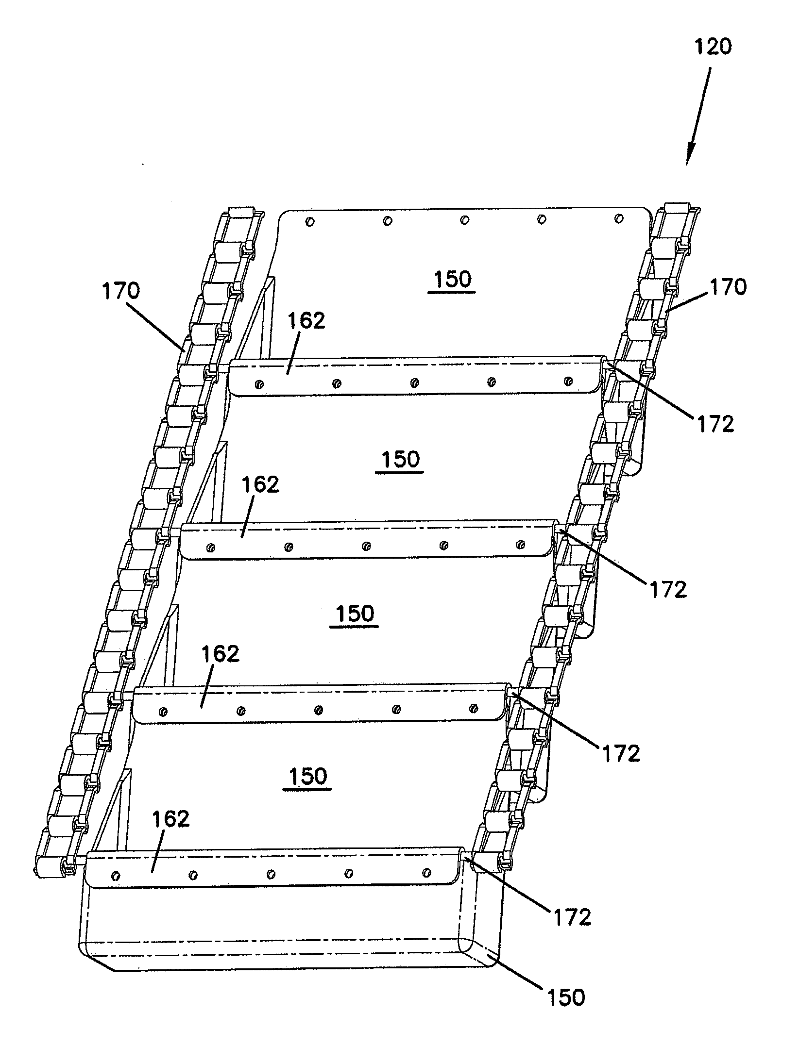
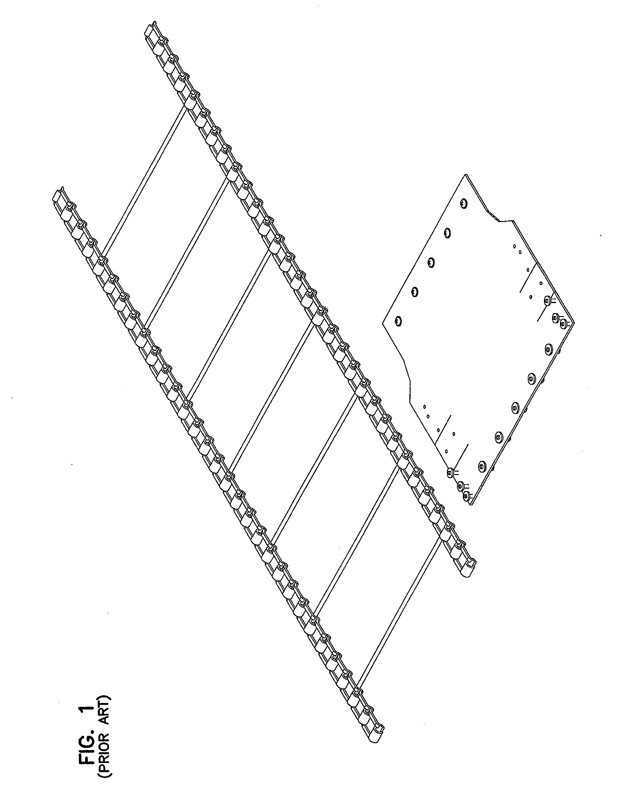
[0045]Referring now to FIGS. 10-13, in a first embodiment, the conveyor 120 includes spaced apart chains 170 with rods 172 extending transversely to the direction of the conveyor run and attaching to each spaced apart chains 170. The chains support buckets 150 that are connected to one another to form a continuous bucket run. The buckets 150 are configured to mount on the rods 172 as shown most clearly in FIG. 13 and to connect to one another in a continuous bucket assembly.
[0046]Referring now to FIGS. 14-16, the buckets 150 are molded buckets of a lightweight plastic material that provide some flexibility. It has been found that a urethane material may be acceptable but other inexpensive, lightweight, durable, moldable materials would also be suitable. Each bucket 150 includes a front wall 154, a rear wall 152, a bottom wall 160 and side walls 156 and 158. The rear wall 152 is higher than the front wall 154 and the side walls 156 and 158 angle upwardly along the top edge to transit...
second embodiment
[0047]Referring now to FIGS. 17-19, buckets 250 may also be used with the conveyor system 120. Each bucket 250 includes a front wall 254, a rear wall 252, a bottom wall 260 and side walls 256 and 258. The rear wall 252 is higher than the front wall 254 and the side walls 256 and 258 angle upwardly along the top edge to transition from the front to the rear wall. A portion of the rear wall 252 extends beyond the side walls 256 and 258 and includes connecting holes 266. Unlike the bucket 150, the front wall 254 is straight rather than having an arcing lip. An upper portion of the front wall 254 is sufficiently flexible that it may be bent over in a manner similar to the molded lip 162 of bucket 150. Orifices 262 and 264 extend through the front wall 254. When assembled, the upper portion of the front wall 254 is folded over the upper edge of the rear wall 256 of an adjacent bucket 250 so that the orifices 262, 264 and 266 are aligned. Adjacent buckets 250 may be mounted to one another...
third embodiment
[0048]Referring now to FIGS. 20-24, buckets 350 may also be used with the conveyor system 120. Each bucket 350 includes a low front wall 354, a rear wall 352, a bottom wall 360 and side walls 356 and 358. The rear wall 352 is higher than the front wall 354 and the side walls 356 and 358 angle upwardly along the top edge to transition from the front to the rear wall. A portion of the rear wall 352 extends beyond the side walls 356 and 358 and includes connecting holes 366. Unlike the bucket 150, the front wall 254 is straight rather than having an arcing lip. However, an insert 360 mounts to the front wall 354 and includes a hook or lip portion 362. The insert 360 may be made of a rigid material that resists wear and corrosion, such as stainless steel. Orifices 364 extend through the front wall 354 and mount the insert 360 and to the rear wall 356 of an adjacent bucket 350, as shown in FIGS. 20-21. When assembled, the upper lip 362 of the insert 360 extends over the upper edge of the...
PUM
 Abstract
Description
Claims
Application Information