Heat exchanger to cool turbine air cooling flow

Active Publication Date: 2010-06-10
PRATT & WHITNEY CANADA CORP
View PDF38 Cites 48 Cited by
  • Summary
  • Abstract
  • Description
  • Claims
  • Application Information

AI Technical Summary

Benefits of technology

[0005]In a further aspect, there is provided a method for active tip clearance control (ATCC) of a turbine, the method comprising the steps of: a) directing a portion of a bypass air flow to cool a portion of a compressor air flow; b) directing the cooled portion of the compressor air flow to cool a surfac

Problems solved by technology

The compressor outlet air (sometimes referred to as “P3” air) usually has a relatively high temperature and a large volume of compressor air is thus required to achieve an effective

Method used


Image

  • Heat exchanger to cool turbine air cooling flow
  • Heat exchanger to cool turbine air cooling flow
  • Heat exchanger to cool turbine air cooling flow

Examples


Embodiment Construction

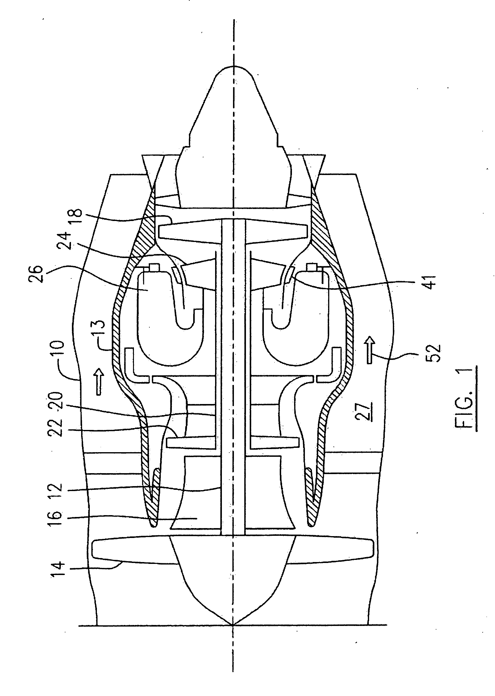
[0013]Referring to FIG. 1, a bypass gas turbine engine includes a housing or nacelle 10, a core casing 13, a low pressure spool assembly (not numbered) which includes a fan assembly 14, a low pressure compressor assembly 16 and a low pressure turbine assembly 18 connected by a shaft 12, a high pressure spool assembly (not numbered) which includes a high pressure compressor assembly 22 and a high pressure turbine assembly 24 connected by a turbine shaft 20. The core casing 13 surrounds the low and high pressure spool assemblies to define a main flow path therethrough. In the main flow path there is provided a combustion gas generator assembly 26 to generate combustion gases for powering the high and low pressure turbine assemblies 24, 18. The housing 10 and the core casing 13 in combination, define an annular bypass air duct 27 to direct a bypass air flow 52 driven by the fan assembly 14 to pass therethrough.

[0014]The terms “axial” and “radial” used for various components below are d...


PUM


Abstract

A cooling system of a gas turbine engine, includes a heat exchanger having a common wall shared by a first air passage for directing a portion of a compressor air flow to be used as cooling air, and a second air passage for directing a portion of a bypass air flow, the portion of the compressor air flow being thereby cooled by the portion of the bypass air flow through the common wall

Description

TECHNICAL FIELD[0001]The application relates generally to a gas turbine engine and more particularly, to a cooling system for gas turbine engines.BACKGROUND OF THE ART[0002]“Active tip clearance control” refers to a gas turbine engine system wherein the radial gap between the turbine blades and surrounding static shroud is varied during the engine cycle in order to optimize tip clearance. Active tip clearance control (ATCC) typically uses compressor or bypass air to selectively cool the turbine shrouds to affect tip clearance. The compressor outlet air (sometimes referred to as “P3” air) usually has a relatively high temperature and a large volume of compressor air is thus required to achieve an effective cooling of the turbine shroud, which is therefore relatively thermodynamically “expensive” for the engine. The use of bypass air for ATCC may be preferred because of its relatively lower temperature, however, bypass air is at a much lower pressure than P3 air, making it more sensit...

Claims


Application Information

Patent Timeline
IPC IPC(8): F01D11/24F02C7/12F02C7/18
CPCF01D11/24F01D25/08F05D2260/20F02C7/185F05D2220/36F02C7/12
Inventor RAGO, GUISEPPE
Owner PRATT & WHITNEY CANADA CORP
Why Eureka
Try Eureka