
Micro-Cutting Machine for Forming Cuts in Products

Active Publication Date: 2010-06-10
SCIENTIA VASCULAR INC
View PDF75 Cites 59 Cited by
  • Summary
  • Abstract
  • Description
  • Claims
  • Application Information

AI Technical Summary

Benefits of technology

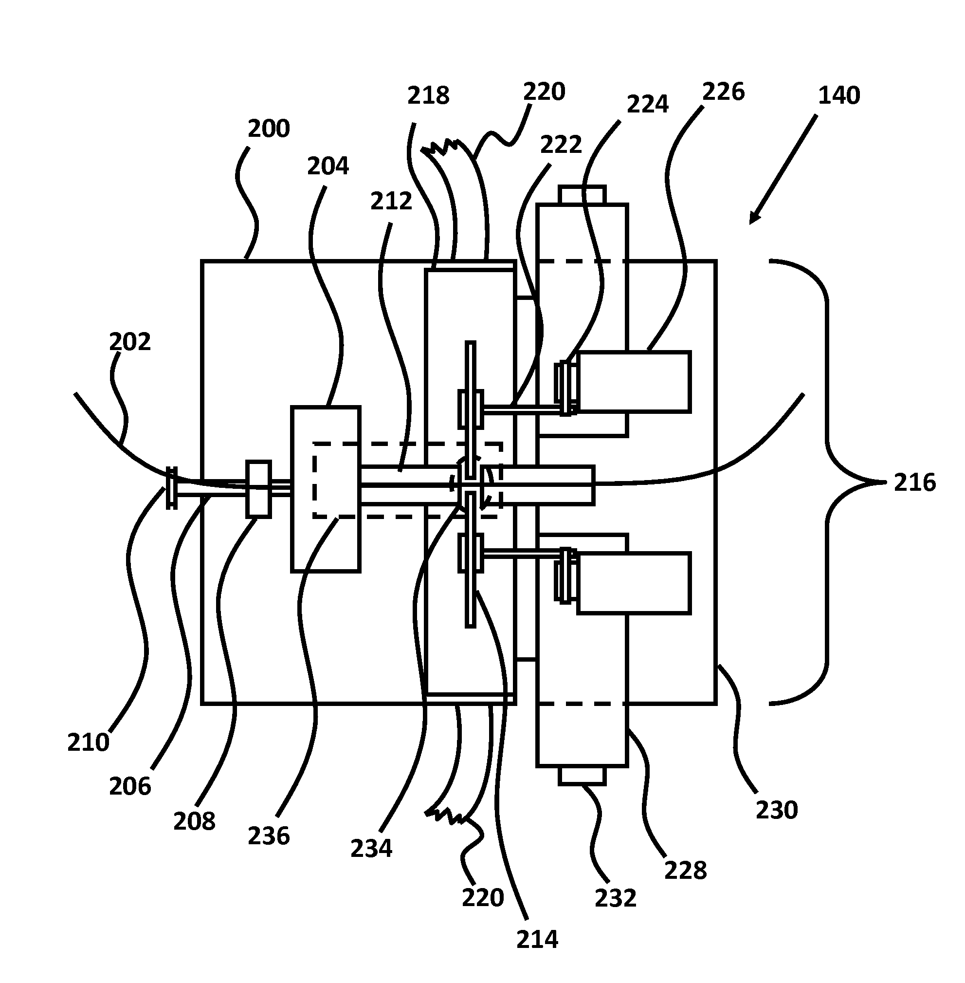
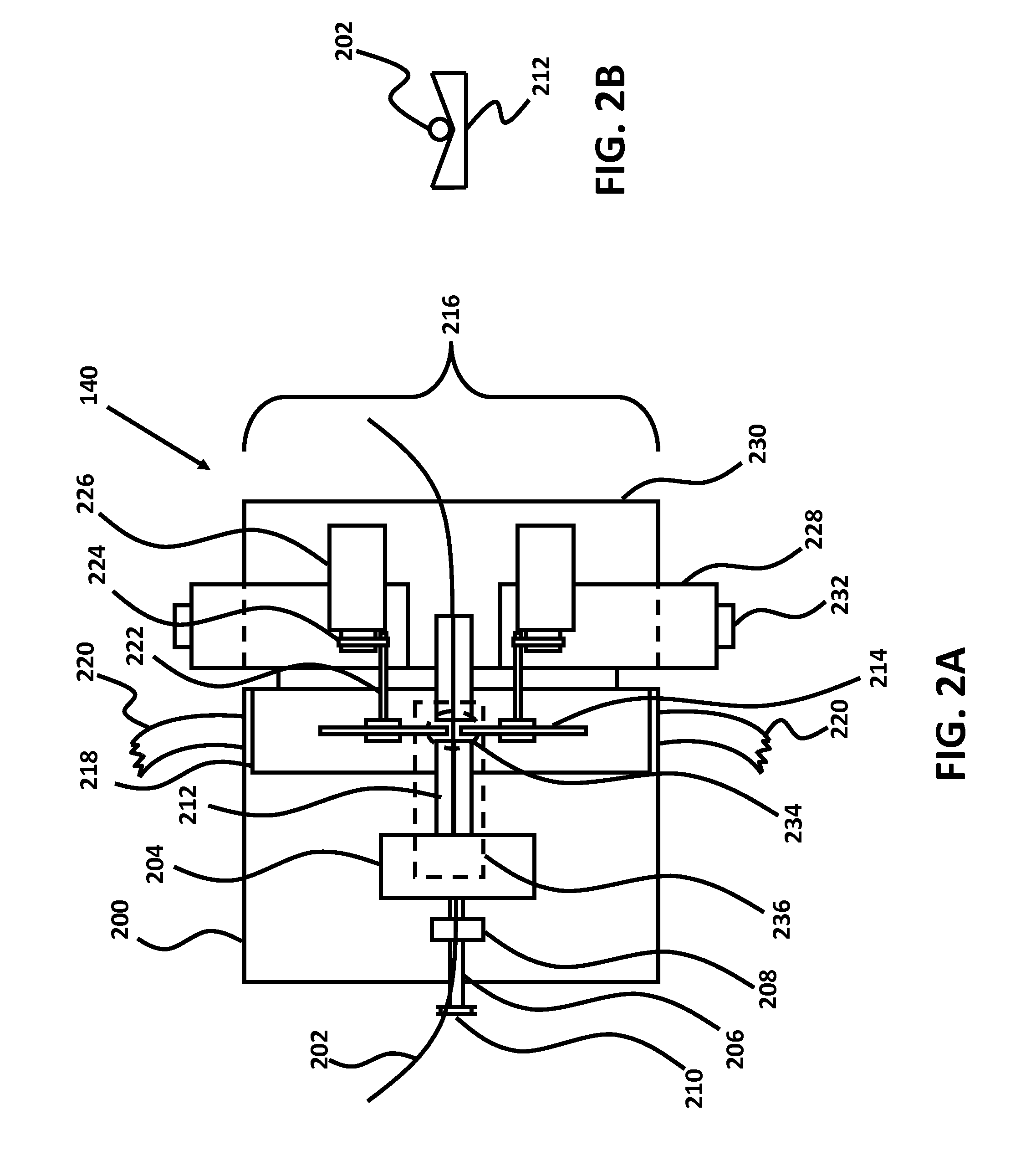
[0009]It would therefore be advantageous to create a micro-cutting machine for machining catheters, guidewires and other devices that utilizes two blades to cut both sides simultaneously, that is able to directly control the width of resultant beams, and that is capable of micro-cutting non-conductive material, such as plastic. Such a machine would be faster, more predictable, and more versatile than current micro-cutting machines.

Problems solved by technology

If blood in the vessels is allowed to “leak,” direct damage can be caused to any tissue outside of the normal capillary approach contacted by the blood, and / or may result in a deadly problem of exsanguination or “bleed out”.
An aneurysm is a very fragile ballooned vessel wall which can easily be punctured if the guidewire or catheter is not precisely controlled.
The guidewires and catheters produced with current technology machines (as described in published patents) have limited functionality.
Due to the single blade design and other aspects of these existing machines, the machines lack the precision necessary to control small (sub 0.002″) features on a reliable basis.
They also lack the ability to precisely control and verify larger features, which could affect the safety and / or performance of these devices.
These machines are also only capable of working with electrically conductive stock material because the machines rely on the electrical conductivity of the stock material to determine the position of the stock relative to the cutting blade.
As the cutting machine is incapable of determining the precise diameter (at the location of the cut) of the stock material being cut, each cut is made according to a preprogrammed depth regardless of that diameter.
This is a problem because stock material is not always of a uniform shape and diameter—there are often imperfections along the length of stock that can affect both the roundness of the stock material and the diameter of the stock material at any particular location.
If the diameter of the stock is thicker than anticipated at the location of the cuts, then the resultant beam will be thicker and therefore less flexible than desired.
If the diameter of the stock is thinner than anticipated at the location of the cuts, then the resultant beam will be thinner and therefore weaker than desired.
This is problematic in terms of both safety and performance of the final product, whether it is a guidewire, catheter or other device.
Existing technology is also unable to cut any kind of non-conductive material, such as plastic.

Method used


Image

  • Micro-Cutting Machine for Forming Cuts in Products
  • Micro-Cutting Machine for Forming Cuts in Products
  • Micro-Cutting Machine for Forming Cuts in Products

Examples


Embodiment Construction

[0017]The herein disclosed micro-cutting machine utilizes a pair of micro-cutting blades or other cutting members to precisely cut into opposing sides of a cylindrical stock material. By cutting both sides simultaneously while tightly controlling the distance between the blades or cutting members, the disclosed micro-cutting machine is capable of producing high performance catheters, guidewires and related products for interventional medical procedures, as well as other devices for a variety of additional uses. While an embodiment has been designed primarily for cutting stock material into flexible and torquable medical guidewires and catheters, the disclosed micro-cutting machine can certainly be used for other applications, and may be appropriate for making precise micro-cuts into a wide variety of cylindrical materials or perhaps even other extruded stock materials which may have non-circular cross-sectional shapes. The micro-cutting machine will mostly be described in regard to ...


PUM

PropertyMeasurementUnit
Angleaaaaaaaaaa
Diameteraaaaaaaaaa
Speedaaaaaaaaaa

Abstract

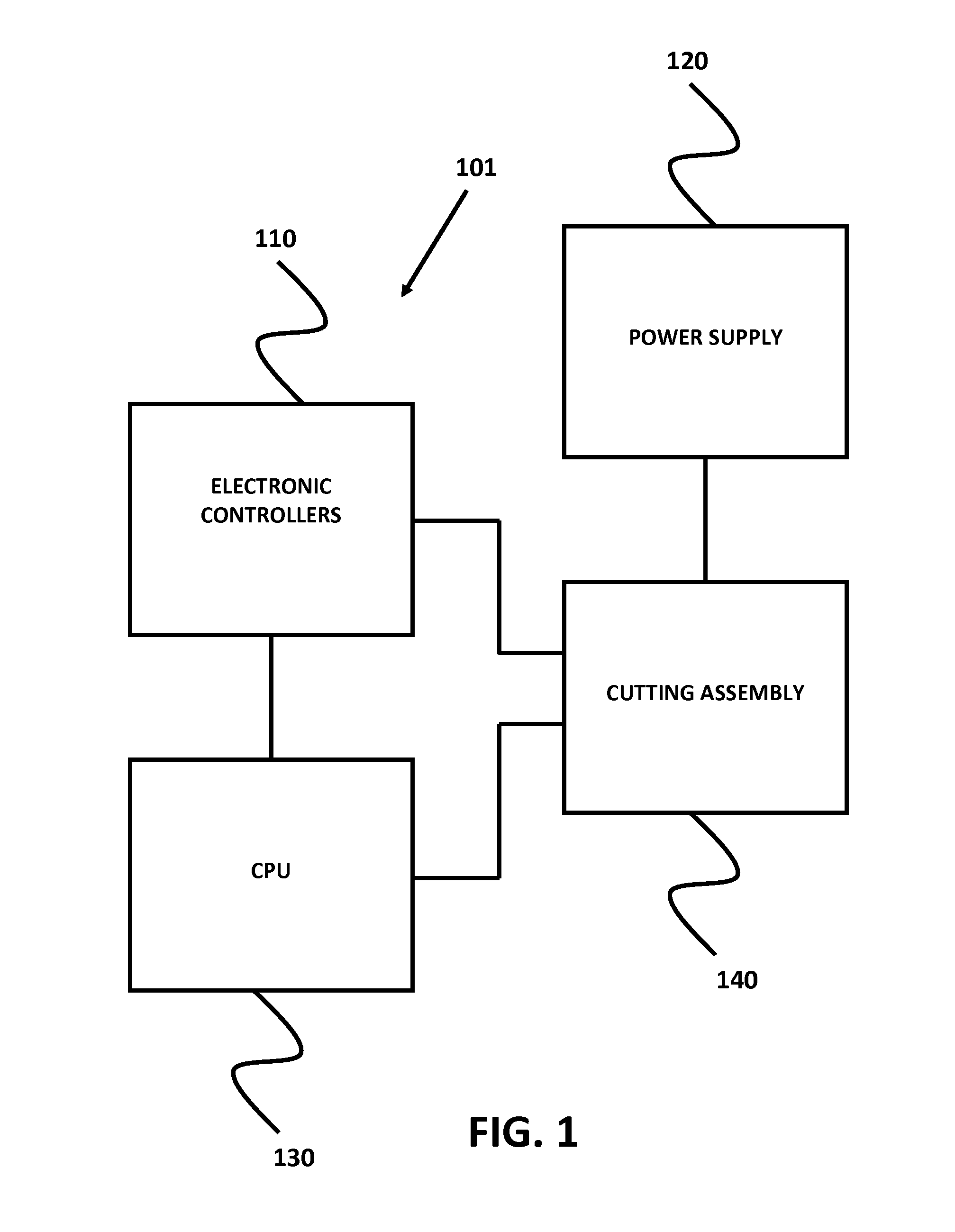
Micro-cutting machines for forming cuts in catheters, guidewires, and similar products, are disclosed, including a micro-cutting machine that can directly control the dimensions of the resultant beams being cut into products, and that can capture images of each cut for feedback control and accuracy verification.

Description

CROSS-REFERENCES TO RELATED APPLICATIONS[0001]This non-provisional application takes priority to provisional applications Ser. No. 61 / 120,703, filed 8 Dec. 2008, and Ser. No. 61 / 166,480, filed 3 Apr. 2009. Both provisional applications are hereby incorporated in their entirety by reference.STATEMENTS AS TO THE RIGHTS TO INVENTIONS MADE UNDER FEDERALLY SPONSORED RESEARCH OR DEVELOPMENT[0002]Not applicable.REFERENCE TO A “SEQUENCE LISTING,” A TABLE, OR A COMPUTER PROGRAM LISTING APPENDIX SUBMITTED ON A COMPACT DISK.[0003]Not applicable.BRIEF DESCRIPTION OF THE INVENTION[0004]Micro-cutting machines for forming cuts in catheters, guidewires, and similar products, are disclosed, including a dual blade micro-cutting machine that can directly control the dimensions of the resultant beams being cut into the products, that can capture images of each cut for feedback control and accuracy verification, and that generally can cut any material (such as plastic) independent of the conductivity of...

Claims


Application Information

Patent Timeline
IPC IPC(8): B26D5/20B26D7/06B26D7/32
CPCA61M25/0015A61M25/09A61M2025/09108B26D5/20B26D7/06B26D7/0683B26F1/0053B26F1/0061B26D5/007B26D5/34B26D1/24B26F1/0076Y10T83/0448Y10T83/051Y10T83/145Y10T83/173Y10T83/4458Y10T83/4463Y10T83/828Y10T83/8878
Inventor CHRISTIAN, JEFFCHRISTIAN, RYANGASBARRO, JAMES A.BOEHMKE, SCOTT K.LIPPERT, JOHN
Owner SCIENTIA VASCULAR INC
Learn More