
Bonding of elastomeric substrate under stretched conditions

a technology of elastomeric substrates and stretched conditions, applied in the direction of layered products, chemistry apparatuses and processes, bandages, etc., can solve the problem of limited ability to form strong ultrasonic bonds using conventional processes, and achieve the effects of efficient bonding of high loft substrates, economical manufacture and use, and suitable bonding

Active Publication Date: 2010-06-10
KIMBERLY-CLARK WORLDWIDE INC
View PDF28 Cites 11 Cited by
  • Summary
  • Abstract
  • Description
  • Claims
  • Application Information

AI Technical Summary

Benefits of technology

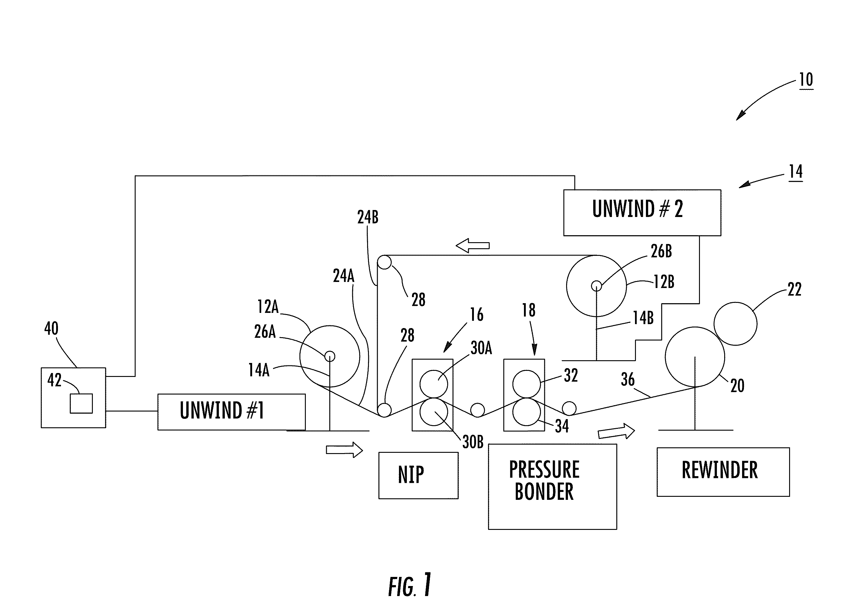
[0004]The present invention is generally directed to a method of bonding high loft substrates efficiently by placing the high loft substrate in a stretched condition in preparation for bonding. According to an aspect of the invention, this can be readily achieved by feeding in less substrate to the process than an amount of substrate being extracted from the process. Generally, a lower loft substrate results, which is more suitable for bonding. The component parts of the bonding system are simple, reliable and economical to manufacture and use. Other advantages of the invention will be apparent from the following description and the attached drawings or can be learned through practice of the invention.

Problems solved by technology

The ability to form strong ultrasonic bonds using conventional processes is limited by several factors, including the process converting speeds or production line speeds, bonding time or dwell time, and the thickness and / or basis weight of the materials being bonded.
Moreover, in the case of rotary ultrasonic or pressure bonding of high loft substrates, bonding pattern roll pins have a tendency of piercing the elastomeric material instead of creating a suitable bond.

Method used


Image

  • Bonding of elastomeric substrate under stretched conditions
  • Bonding of elastomeric substrate under stretched conditions
  • Bonding of elastomeric substrate under stretched conditions

Examples


example

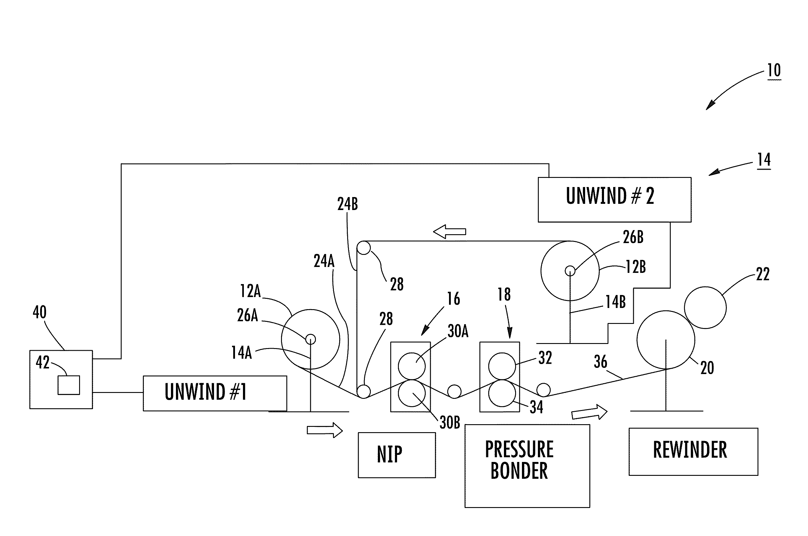
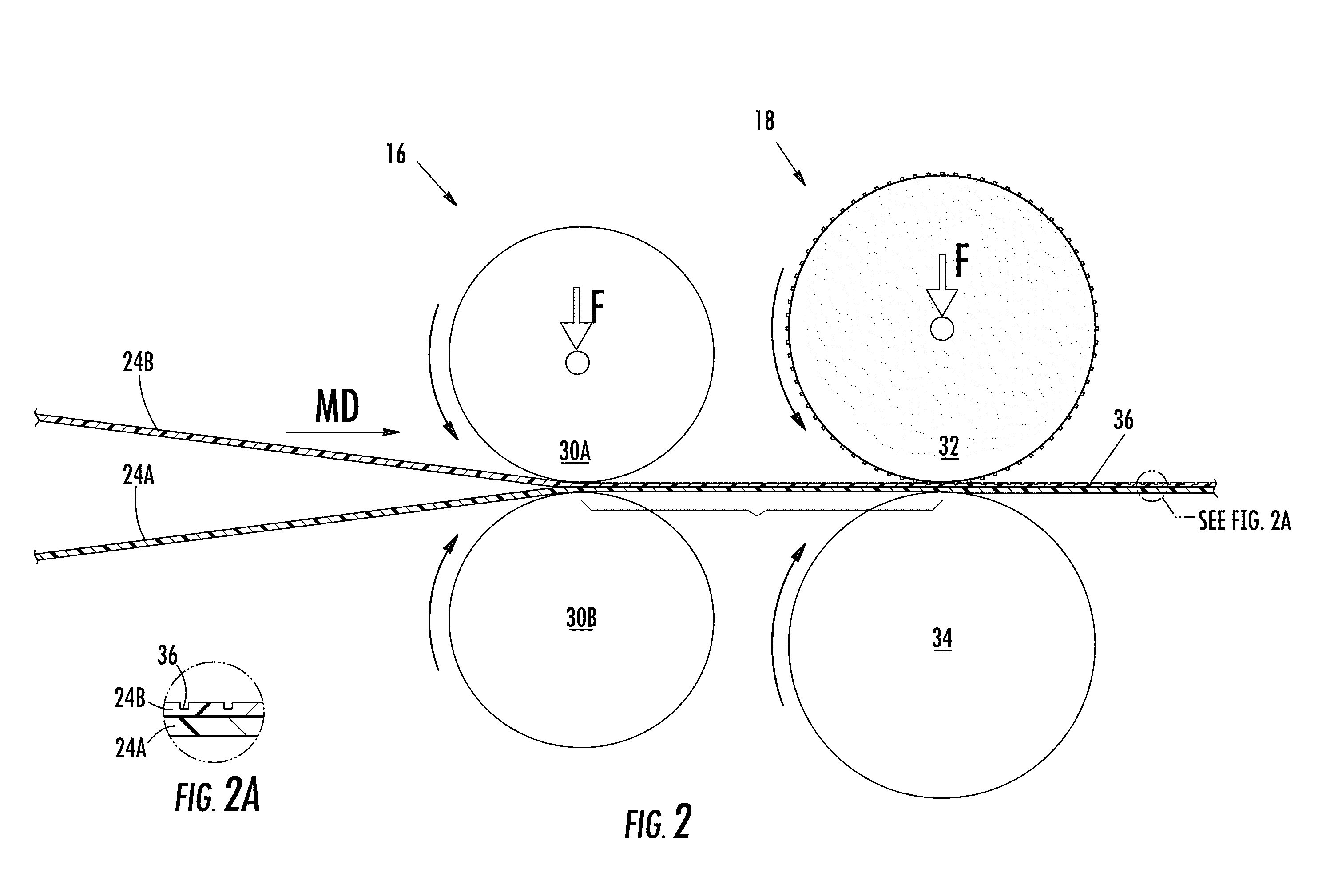
[0069]The following example was performed in order to determine the effect of stretching webs of material, such as webs 24A, 24B discussed herein, prior to bonding using a bonder such as the bonder 18 as shown in FIG. 1. At least one of the webs of material 24A, 24B was unwound into the nip 16, specifically between the rolls 30A, 30B and stretched prior to the pressure bonder 18 and the rewinder 20. The pressure bonder 18 and the rewinder 20 were processing at a line speed approximately twice that of the unwind system 14 and the nip 16.

[0070]Stated another way, the pressure bonder 18 and the rewinder 20 took away the material 24A, 24B at a speed twice that of the nip 16 prior to the pressure bonder 18, which ensured that the material 24A, 24B was in a stretched state at the bonder 18. Thirty samples were produced and tested. As shown in the following charts, various product speeds per minute—assuming a product pitch of 29 inches based on the trial pressure bonder—were employed for t...


PUM

PropertyMeasurementUnit
elongationaaaaaaaaaa

Abstract

A method of bonding material in a process system for producing a bonded product includes the steps of loading a plurality of rolls of elastomeric material in an unwind system; programming a controller with an unwind speed and a rewind speed, the controller in communication with the unwind system and a rewinder disposed downstream from the unwind system for respective communication of the unwind and rewind speeds to the unwind system and the rewinder; unwinding a quantity of material from the plurality of rolls of elastomeric material into a pressure bonder disposed upstream of the rewinder, the pressure bonder and the rewinder operating faster than the unwind system operating at the unwind speed to generate a speed differential, wherein the speed differential imparts a stretch state to the quantity of material; and bonding the stretched quantity of material with the pressure bonder.

Description

BACKGROUND OF THE INVENTION[0001]Disposable garments, such as infant and children's diapers, swimwear and training pants, as well as adult incontinence garments, conventionally include materials that are joined together and connected using a bonding process, or the materials are bonded in related converting systems prior to bonding the materials together. For example, a training pant or other pant-type garment may have a front side panel and a back side panel that are bonded together at a side seam to provide a complete side panel. The side panels are typically connected at the side seam using an ultrasonic process such as the process described by You et al. in U.S. Pat. App. Pub. No. 2005 / 0133144 A1.[0002]The ability to form strong ultrasonic bonds using conventional processes is limited by several factors, including the process converting speeds or production line speeds, bonding time or dwell time, and the thickness and / or basis weight of the materials being bonded. Moreover, in ...

Claims


Application Information

Patent Timeline
Patent Type & Authority Applications(United States)
IPC IPC(8): B32B38/00B29C55/06
CPCA61F13/15593B32B38/1825B32B2309/14B32B2307/51B32B2038/0028
Inventor NORDANG, LARS N.
Owner KIMBERLY-CLARK WORLDWIDE INC
Learn More