Hydrulic breaker assembly

a technology of breaker assembly and hydraulic breaker, which is applied in the direction of manufacturing tools, percussive tools, portable drilling machines, etc., can solve the problems of deteriorating the reliability of the connection, increasing the shear load applied to the long bolts, and degrading durability, so as to reduce the vibration and impact noise of the breaker, the effect of reducing the impact generation section and improving the durability

Active Publication Date: 2010-06-10
KIM JAE MOG
View PDF7 Cites 13 Cited by
  • Summary
  • Abstract
  • Description
  • Claims
  • Application Information

AI Technical Summary

Benefits of technology

[0016]In the hydraulic breaker assembly according to the present invention, the head cap, the cylinder, and the front head are prevented from moving in the casing and are firmly combined, the length of the long bolt is shortened to minimize an impact-generating section and protect the long bolt from the distortion stress generated upon the striking of the rod, hence improving the durability, and impact vibrations and impact noise of the breaker are reduced to safely protect respective dampers from friction abrasion and friction heat.
[0017]Further, the front head, the cylinder, and the head cap are constantly supported in position in order to lower the error rate of the breaker assembly and to increase the lifetimes of the respective dampers and the breaker assembly.
[0018]Furthermore, the error rate of the hydraulic breaker assembly is reduced due to its strong assembly which thereby considerably elongates the useful lifetime of a product.

Problems solved by technology

However, such a breaker has a problem in that, when distortion stress occurs in the striking rod upon striking rocks or the like, the distortion stress is concentrated on connecting portions between the front head and the cylinder and between the cylinder and the head cap, so that the stress is applied to the long bolts threaded through the connecting portions, causing deformation such as bending or breakage, thereby deteriorating the reliability of the connection.
Further, another problem is that the construction of the plurality of variable dampers 30-1, 30-2, 40-1, and 50-1, which are provided on the inside of the casing 60 so as to support the front head 40, the cylinder 50, and the head cap 30, respectively, suffers from abrasion resulting from friction caused by vibrations or the like, which increases the shear load applied to the long bolts 80, thereby degrading the durability thereof.
However, such a hydraulic breaker has problems as follows.
Since the urethane members become damaged due to frequent vibrations and impacts, gaps are created between the assembly body and the side dampers, generating noise and vibrations.
Since the piston cannot accurately strike the chisel as the gaps expand gradually, the damage to the assembly body is accelerated, and the durability and reliability of a product are reduced.
Since all the side dampers have to be replaced when eccentric abrasion occurs, unnecessary waste is caused.

Method used


Image

  • Hydrulic  breaker assembly
  • Hydrulic  breaker assembly
  • Hydrulic  breaker assembly

Examples


Embodiment Construction

[0026]Reference will now be made in greater detail to an exemplary embodiment of the invention, which is illustrated in the accompanying drawings.

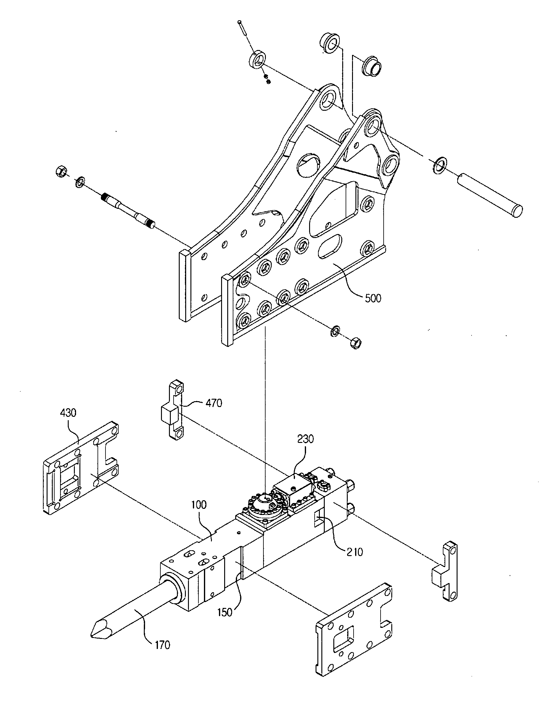
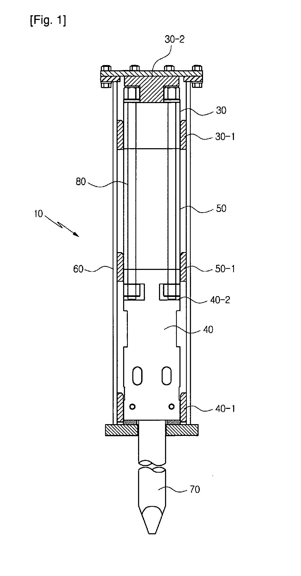
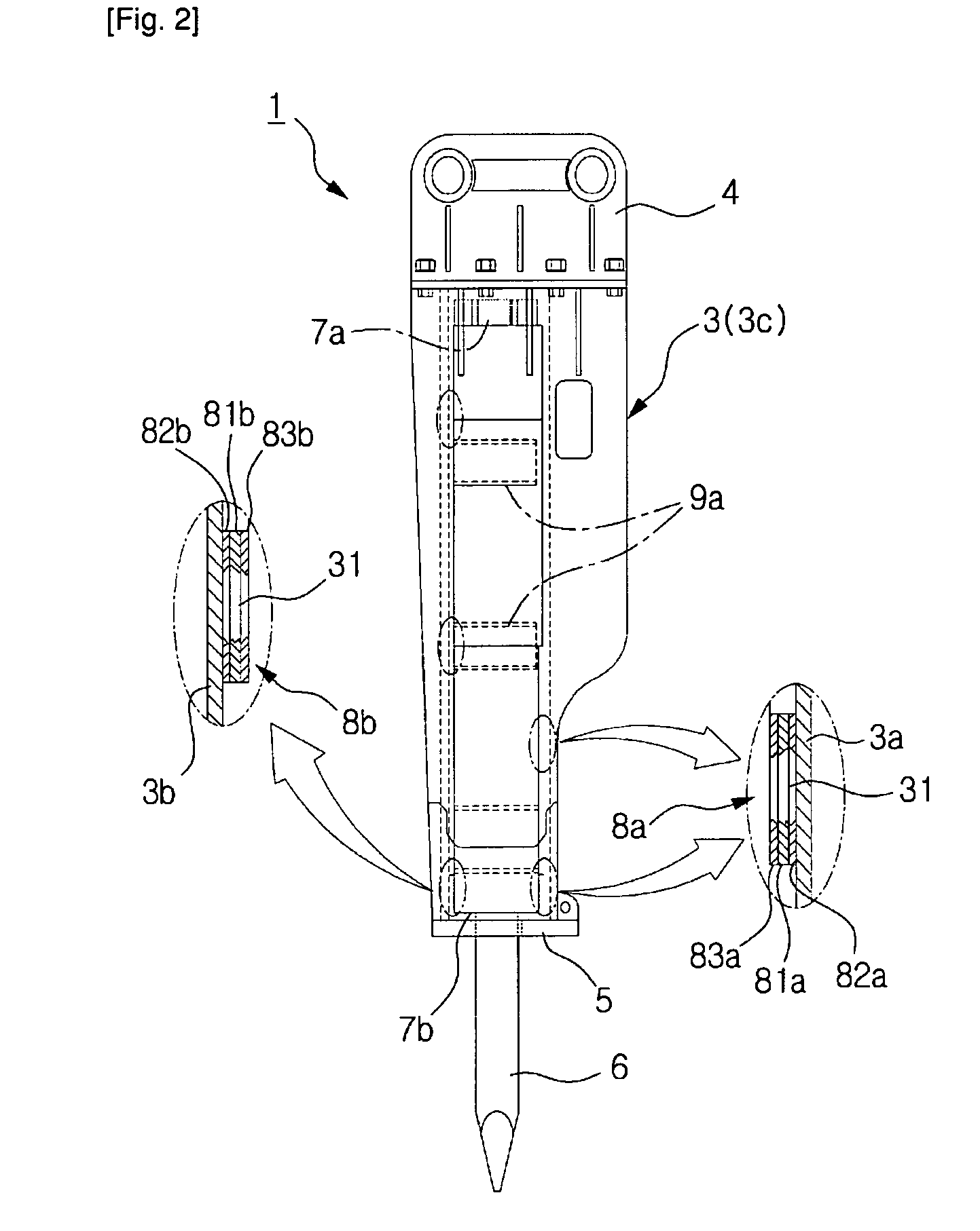
[0027]FIGS. 3 and 4 are views illustrating the states in which a hydraulic breaker assembly according to the present invention is disassembled and assembled. FIG. 5 is a partial exploded cross sectional view illustrating the hydraulic breaker assembly according to the present invention. FIG. 6 is a partial cross sectional view illustrating the state in which a damper is mounted in a hydraulic breaker assembly according to another embodiment of the present invention. FIGS. 7 and 8 are schematic views illustrating the adaptations of dampers according to the present invention. FIGS. 9 and 10 are a cross sectional view and a partially enlarged view respectively illustrating the states in which a rod is mounted in a hydraulic breaker assembly according to another embodiment of the present invention.

[0028]In the hydraulic breaker assembly of the...


PUM

PropertyMeasurementUnit
pneumatic pressureaaaaaaaaaa
pressure lossaaaaaaaaaa
compression forceaaaaaaaaaa

Abstract

A hydraulic breaker assembly including a head cap, a cylinder, and a front head, which arc mounted in a casing, wherein corresponding faces of the front head and the cylinder are connected by connecting pins, wherein the cylinder and the head cap located above the cylinder are fixed together by fastening bolts, and wherein the front head, the cylinder, and the head cap are supported on an inner side of the casing by variable dampers, which are brought into close contact with the front head, the cylinder, and the head cap. The movement in the casing is thus prevented so that the head cap, the cylinder, and the front head are strongly coupled together. The length of the fastening bolt is reduced to minimize the impact-generating section so that the bolt is protected from distortion stress occurring upon striking of the rod, thereby increasing durability.

Description

TECHNICAL FIELD [0001]The present invention relates, in general, to a hydraulic breaker assembly which improves an assembly structure including a head cap, a cylinder, and a front head, which are assembled in a casing, thereby increasing the durability thereof.BACKGROUND ART[0002]As is generally known in the art, a hydraulic breaker includes a head cap having hydraulic passages for supplying and receiving hydraulic pressure, a cylinder having a cylinder chamber, in which a piston is reciprocated, and elements, e.g. valves or the like, for operating the piston, and a front head having a striking rod, which is connected to the piston so as to implement a striking stroke through reciprocating operation. The above constitutional elements are separately formed and are combined into a single unit by four long bolts. In operation, the piston strikes the rod while moving up and down by means of hydraulic pressure supplied to the cylinder, so that the rod can break a rock or the like.[0003]A...

Claims


Application Information

Patent Timeline
Patent Type & Authority Applications(United States)
IPC IPC(8): B25D9/04B25D9/06B25D9/14B25D9/26
CPCB25D17/00E02F5/305B25D2250/121E02F3/966
Inventor KIM, JAE-MOG
Owner KIM JAE MOG
Why Eureka
Try Eureka