Knee joint implant preventing hyperextension

a knee joint and implant technology, applied in knee joints, knee prosthesis, medical science, etc., can solve the problems of knee joint hyperextension, knee joint excessive backwards bending, severe pain, etc., and achieve the effect of preventing the patient's behavior itself and preventing further hyperextension

Active Publication Date: 2020-09-22
CORENTEC
View PDF2 Cites 0 Cited by
  • Summary
  • Abstract
  • Description
  • Claims
  • Application Information

AI Technical Summary

Benefits of technology

[0019]An aspect of the present disclosure is to provide a knee joint implant, in which, in the state in which a knee is extended, the femoral component having a convex condyle slides and a plurality of contact points are provided on the bearing component having a concave articular surface, whereby even if an elderly patient having aged muscles and ligaments undergoes a TKR operation, the occurrence of a hyperextension phenomenon can be suppressed.
[0062]The present disclosure provides a knee joint implant, in which the fourth angle of the bearing component is set to be smaller than the fifth angle such that the section in which the condyle of the femoral component slides on the articular surface of the bearing component is minimized, thereby preventing the patient's behavior itself from becoming unnatural.

Problems solved by technology

When the cartilage is damaged due to extreme exercise, aging, or the like, bone and bone may come into direct contact with each other, which causes severe pain.
One of the problems with the TKR operation is that the knee is hyperextended in a patient who has undergone the TKR operation and eventually genu recurvatum (back-knee), which is a symptom in which the knee joint is excessively bent backwards, occurs.
Thus, weak muscles may cause problems.
This problem may also be caused by problems in terms of the shape of the femoral component and the bearing component used in the conventional TKR operation.
However, in the case of elderly patients with weak muscles and ligaments, the strength of the muscles and ligaments may be insufficient and thus the knees may be inevitably hyperextended.

Method used


Image

  • Knee joint implant preventing hyperextension
  • Knee joint implant preventing hyperextension
  • Knee joint implant preventing hyperextension

Examples


Embodiment Construction

[0079]Hereinafter, embodiments of a knee joint implant that prevents hyperextension according to the present disclosure will be described in detail with reference to the accompanying drawings. In the following description of the present disclosure, a detailed description of known functions or configurations will be omitted when it is determined that the detailed description may make the subject matter of the present disclosure rather unclear. Unless defined otherwise, all terms used herein have the same meanings as general meanings of terms understood by a person ordinarily skilled in the art to which this disclosure belongs, and when the general meanings conflict with the meanings of the terms used herein, the meanings of the terms follow the definition used in the specification.

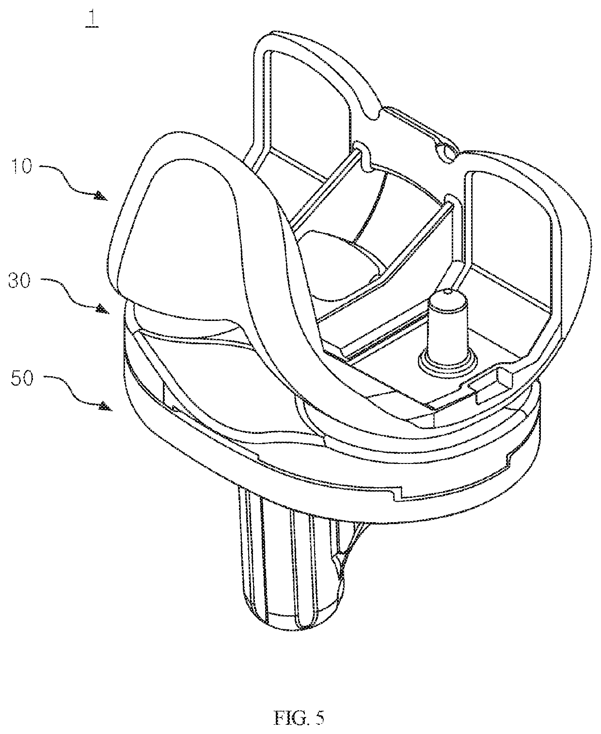
[0080]In this specification, the drawings are illustrated on the basis of a knee joint implant to be inserted into a left knee of a patient.

[0081]FIG. 5 is a perspective view illustrating a knee joint impla...


PUM


Abstract

A knee joint implant that prevents hyperextension includes a femoral component having an anterior surface with reference to the lowermost point of a convex condyle, the anterior surface being configured to have different curvature radii in respective sections thereof, and a bearing component having an anterior surface with reference to the lowermost point of a concave articular surface, the anterior surface being configured to have different curvature radii in respective sections, so that when an extended knee is about to be hyperextended, the convex condyle of the femoral component slides toward the anterior side and is brought into contact with a plurality of points of the concave articular surface of the bearing component, thereby producing resistance so as to suppress hyperextension exceeding a design range due to behavioral habits, a decrease in muscle mass, and the like of the patient.

Description

CROSS-REFERENCE TO RELATED APPLICATIONS[0001]This application claims priority to Korean Application No. 10-2018-0092366, filed Aug. 8, 2018, the entire contents of which is incorporated herein by specific reference.BACKGROUND OF THE INVENTION1. Field of the Invention[0002]The present disclosure relates to a knee joint implant that prevents hyperextension, and more particularly to a knee joint implant that prevents hyperextension, in which the knee joint implant includes a femoral component having an anterior surface with reference to the lowermost point of a convex condyle, the anterior surface being configured to have different curvature radii in respective sections thereof, and a bearing component having an anterior surface with reference to the lowermost point of a concave articular surface, the anterior surface being configured to have different curvature radii in respective sections, so that when an extended knee is about to be hyperextended, the convex condyle of the femoral c...

Claims


Application Information

Patent Timeline
Patent Type & Authority Patents(United States)
IPC IPC(8): A61F2/38A61F2/30A61F2/46
CPCA61F2/3877A61F2/385A61F2/461A61F2/3886A61F2/389A61F2/3859A61F2002/30001A61F2/3836A61F2/3868
Inventor JANG, YOUNG-WOONGKIM, CHAN-EOLRO, JAE-HUNHAN, AH-REUMLEE, MYUNG-CHULIN, YONGHAN, SEUNG-BEON
Owner CORENTEC
Why Eureka
Try Eureka