Noise Reduction in Capacitive Touch Sensors

a capacitive touch sensor and capacitive technology, applied in the field of capacitive touch sensor noise reduction, can solve the problems of affecting the operation of the touch sensor on the mobile phone, so as to avoid a frame being compromised, improve the effect of data quality and improve the effect of accuracy

Active Publication Date: 2010-06-10
NEODRON LTD
View PDF29 Cites 92 Cited by
  • Summary
  • Abstract
  • Description
  • Claims
  • Application Information

AI Technical Summary

Benefits of technology

[0023]The invention is particularly beneficial for two dimensional touch sensors with an m x n grid of X and Y lines, such as are used as overlays for displays or other touch panels. In particular, the invention avoids the situation where a considerable amount of time is wasted obtaining a frame of touch data relati

Problems solved by technology

Although touch sensitive capacitive sensors such as those described above and disclosed in the above-mentioned disclosures have been successfully deployed in many applications, some applications can present a challenging environment for detecting a change in charge as a result of the presence of a body.
For example, the use of a touch sensor on a mobile phone can create a technical problem because there is a variety of disturbing noise signals produced by radio frequency radiation, by radio frequency signals and by modulators within the mobile phone.
Similarly, a liquid crystal display (LCD) has characteristic switching noise as a result of switching and refreshing pixels.
Other types of display may have their own forms of characteristic impulsive noise related to pixel scanning and refresh.
Sinusoidal noise, such as that produced by mains electricity may also be present, which can affect the amount of charge detected on a key.
As will be appreciat

Method used


Image

  • Noise Reduction in Capacitive Touch Sensors
  • Noise Reduction in Capacitive Touch Sensors
  • Noise Reduction in Capacitive Touch Sensors

Examples


Embodiment Construction

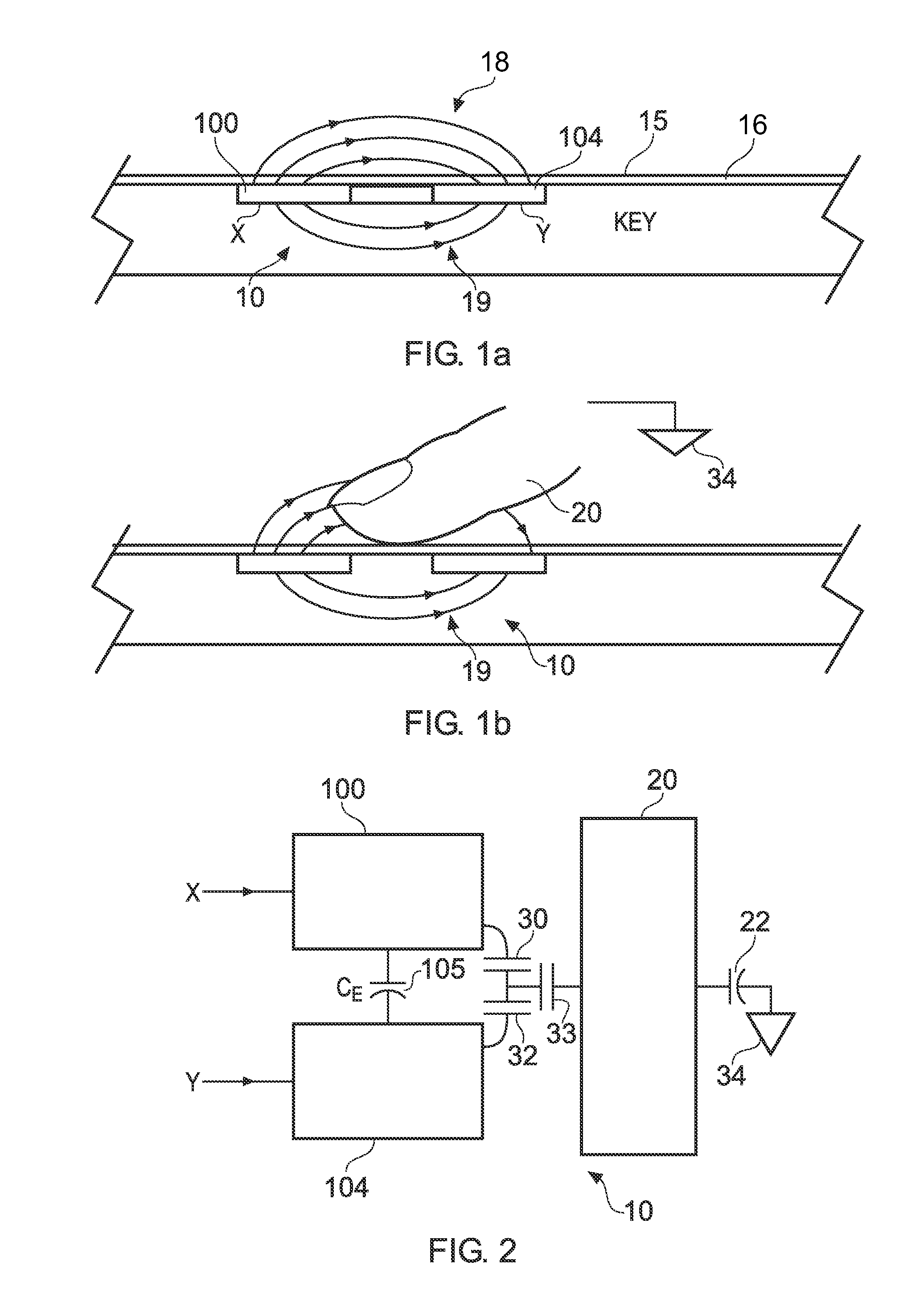
[0037]FIG. 1a is a schematic cross-section through a touch sensitive control panel 15 in the absence of an actuating body, typically a user's finger or stylus.

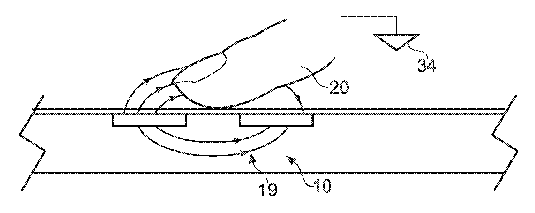
[0038]FIG. 1b corresponds to FIG. 1a, but shows the same cross-section in the presence of an actuating body in the form of a user's finger.

[0039]The touch sensor shown in FIGS. 1a and 1b correspond to an example in which a pair of transverse electrodes form a touch sensor. As shown in FIG. 1a a pair of electrodes 100, 104 which form a drive or X plate and a receiving or Y plate in the following description are disposed beneath the surface of a touch sensitive control panel 15. The electrodes 100, 104 are disposed beneath a dielectric layer 16, for example a glass or plastics panel. As shown in FIGS. 1a and 1b the touch sensor 10 is arranged to detect the presence of a body such as a user's finger 20 as a result of a change in an amount of charge transferred from the Y plate 104. As shown in FIG. 1a when the X plate 100 is char...


PUM


Abstract

Noise reduction in a one- or two-dimensional capacitive sensor array is achieved by rejecting and re-acquiring noisy signals. The sensor array is formed of crossed X and Y lines for drive and sense functions respectively, each of the X lines being driven in turn to acquire a full frame of data from the sensor array. A controller actuates the X lines in turn and, for each X line, charge is transferred to charge measurement capacitors connected to respective ones of the Y lines. The controller measures a signal value from a first one of the measurement capacitors, and then tests if that Y signal value has a magnitude lying within an acceptable range. If not, the measurement capacitors are all reset without their signal values being measured, and the controller re-drives the same X line to initiate another charge transfer into the measurement capacitors for that X line. It is then attempted once again to acquire Y signal values for that X line. Noisy signal values are thus rejected, and the sensor re-acquires substitute signal values. This is distinct from the approach of acquiring data and then reprocessing it to remove or suppress noisy data as in the prior art.

Description

BACKGROUND OF THE INVENTION[0001]The present invention relates to noise reduction in a capacitive touch sensor for detecting proximity and location of a body, more especially to a one- or two-dimensional capacitive sensor of the so-called active type which is based on measuring the capacitive coupling between two electrodes at each sensing node in a detector array.[0002]There are various forms of touch sensitive controls which use a capacitive sensor to sense the presence of a body such as a user's finger. A form of touch sensitive control is disclosed in WO-00 / 44018. In this example a pair of electrodes are provided which act as a key so that the presence of a body such as a user's finger is detected as a result of a change in an amount of charge which is transferred between the two electrodes. With this arrangement, one of the electrodes (labelled X) is driven with a drive circuit and the other of the pair of electrodes (labelled Y) is connected to a charge measurement circuit whi...

Claims


Application Information

Patent Timeline
IPC IPC(8): G06F3/044
CPCG06F3/0418G06F3/044H03K2217/960725H03K2217/960705H03K17/962G06F3/0443G06F3/0446
Inventor PHILIPP, HARALDYILMAZ, ESAT
Owner NEODRON LTD
Why Eureka
Try Eureka