Imaging system and method with scatter correction

a scatter correction and imaging system technology, applied in the field of non-invasive imaging, can solve the problems of not being able to measure internal features, ct based techniques may also have limitations, and deter their widespread us

Active Publication Date: 2010-06-10
GENERAL ELECTRIC CO
View PDF25 Cites 30 Cited by
  • Summary
  • Abstract
  • Description
  • Claims
  • Application Information

AI Technical Summary

Problems solved by technology

Modalities such as CMM and laser-based profilometry typically measure external surfaces with high accuracy, but cannot measure internal features unless the object is cut open.
However, CT based techniques may also have certain limitations, which may deter their widespread use.
For example, volumetric computerized tomography (VCT) imaging for industrial applications (e.g., imaging of metallic parts) typically provides unsatisfactory images having image artifacts due to radiation-matter interaction based artifacts, scanner based artifacts, reconstruction techniques based artifacts, and so forth.
Scatter radiation in the projection images reduces the contrast of the projection images, produces degradation of or blurs sharp features of the object in the generated volume images, and reduces the accuracy of metrology applications and the detectability of smaller features.
Due to various dependencies in the imaging parameters, an accurate estimation of the scatter signal content in projection imaging is challenging.
Physics-based models are often used for predicting scatter content in x-ray images, however they are time consuming and predict only scatter arising out of the object under scanning, provided the material properties are known.
However, most currently known techniques primarily address the object scatter and involve time-consuming computer simulations.

Method used


Image

  • Imaging system and method with scatter correction
  • Imaging system and method with scatter correction
  • Imaging system and method with scatter correction

Examples


Embodiment Construction

[0017]The present techniques are generally directed to computed tomography (CT) imaging resulting in improved image quality. Such imaging techniques may be useful in a variety of imaging contexts, such as medical imaging, industrial metrology and inspection, security screening, baggage or package inspection, and so forth. Moreover, such imaging techniques may be employed in a variety of imaging systems, such as CT systems, tomosynthesis systems, X-ray imaging systems, and so forth. Though the present discussion provides examples in an industrial inspection context with respect to CT systems resulting in improved measurement and inspection accuracy, one of ordinary skill in the art will readily apprehend that the application of these techniques in other contexts and in other systems is well within the scope of the present techniques.

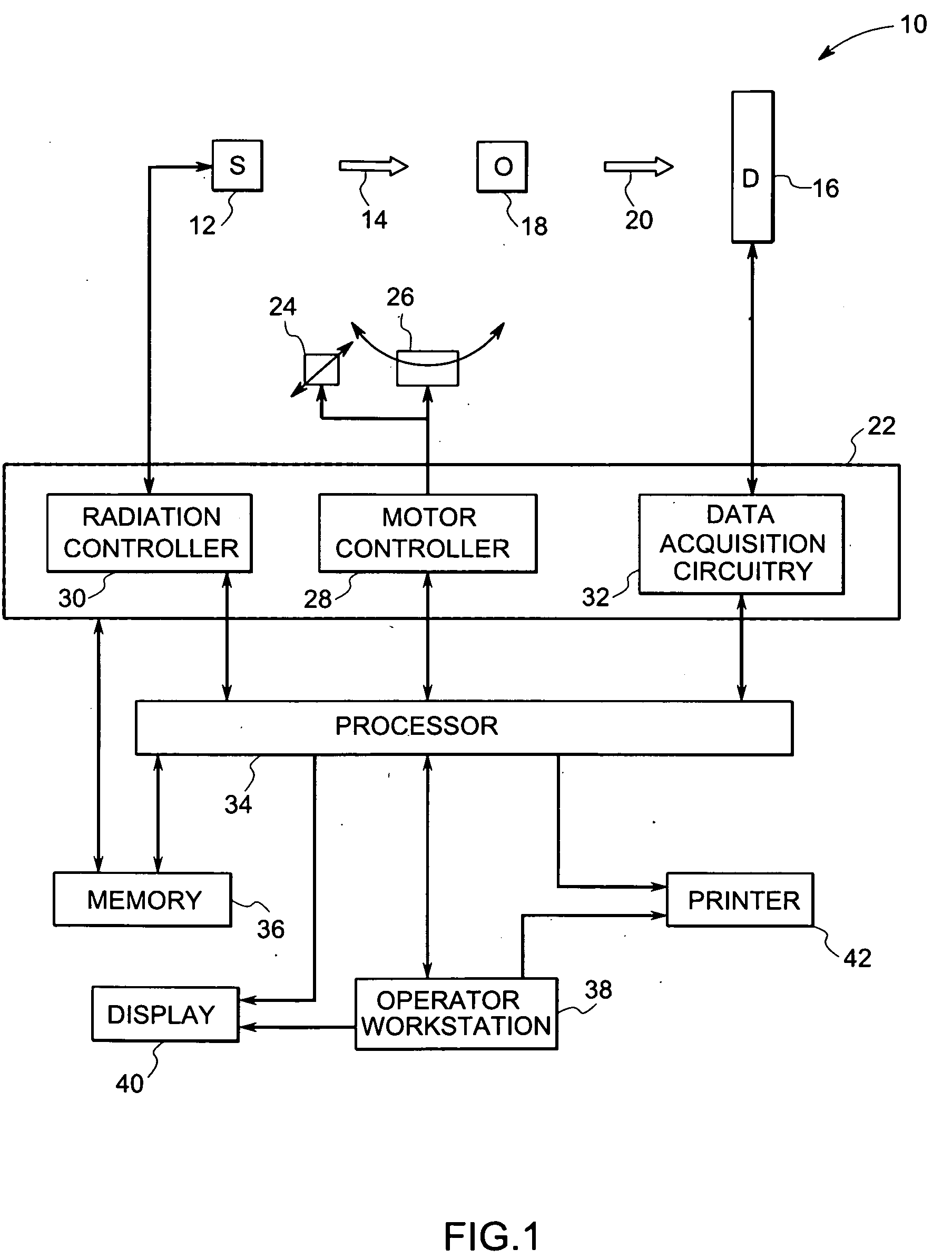
[0018]Referring now to FIG. 1, an imaging system 10 for use in accordance with the present technique is illustrated. In the illustrated embodiment, the i...


PUM


Abstract

An imaging technique is provided for acquiring scatter free images of an object. The technique includes acquiring a plurality of projection images of the object using a source and a detector oriented at a plurality of projection angles relative to the object, and generating a plurality of scatter free projection images by correcting the plurality of projection images based on respective ones of a plurality of stored scatter images. The scatter images are generated and stored for each of the projection angles by positioning a scatter rejection plate between the object and the detector. The technique further includes reconstructing a three-dimensional image of the object based on the scatter free projection images.

Description

BACKGROUND[0001]The invention relates generally to the field of non-invasive imaging and more specifically to the field of computed tomography (CT) imaging and inspection systems. In particular, the invention relates to a technique for correcting scatter from digital radiographs acquired via volumetric computed tomography (VCT) systems.[0002]Inspection of objects is of vital importance in manufacturing and repair industries. Various types of inspection systems, such as computed tomography (CT), coordinate measuring machines (CMM), laser-based profilometry, light gauge, infrared and others, are used in industrial inspection processes for a wide variety of applications. For example, these inspection systems may be used for measuring dimensions or for identifying defects in manufactured parts, such as turbine blades. Each of these inspection systems has its advantages and disadvantages. Modalities such as CMM and laser-based profilometry typically measure external surfaces with high ac...

Claims


Application Information

Patent Timeline
Patent Type & Authority Applications(United States)
IPC IPC(8): G21K1/02
CPCH04N5/32G01N23/046G01N2223/316A61B6/5282
Inventor MISHRA, DEBASISHROSS, WILLIAM ROBERTBATZINGER, THOMAS JAMESVENUGOPAL, MANOHARANHOPKINS, FORREST FRANKGOPALIKA, NITYANANDKOMMAREDDY, VAMSHI KRISHNA REDDYVENKATACHALAM, RAJASHEKARTHAPA, PRASAD
Owner GENERAL ELECTRIC CO
Why Eureka
Try Eureka