Spread-period clock generator

a pulse train and generator technology, applied in the direction of pulse generation with predetermined statistical distribution, pulse automatic control, pulse technique, etc., can solve the problem of not being able to assign a distinct waveform to each waveform

Inactive Publication Date: 2010-06-10
MITSUBISHI ELECTRIC CORP
View PDF6 Cites 46 Cited by
  • Summary
  • Abstract
  • Description
  • Claims
  • Application Information

AI Technical Summary

Benefits of technology

[0033]A spread-period clock generator according to the invention counts basic clock pulses to generate output pulses with varying periods, and has means for switching between a first mode, in which counting is carried out in response to the leading edges of the basic clock pulses, and a second mode, in which counting is carried out in response to the trailing edges of the basic clock pulses. Accordingly, if mode switching is carried out during a counting operation, the counting period is altered by a portion of a basic clock period. Thus, the number of different periods of the output pulses can be increased without increasing the basic clock frequency and without glitches occurring in the output.

Problems solved by technology

Because it is not possible to predict which of the many similar systems will be operating in a particular environment, it is not practical to assign a distinct waveform to each of them.

Method used


Image

  • Spread-period clock generator
  • Spread-period clock generator
  • Spread-period clock generator

Examples


example

[0081]Assume that an initial ‘negative’ state {C0} of the counter SBC has been selected as

{C0}={1 1 1 0 1}

[0082]Neither of the first four ‘non-positive’ counter states

{1 1 1 0 1}, {1 1 1 1 0}, {1 1 1 1 1}, {0 0 0 0 0}

corresponds to one of the allowable ‘positive’ LFSR states; therefore, the shortest time interval will be obtained when {S*}={0 0 0 1}. The above four states will form the preamble associated with the selected initial SBC state {C0}, which will determine the duration of the shortest time interval.

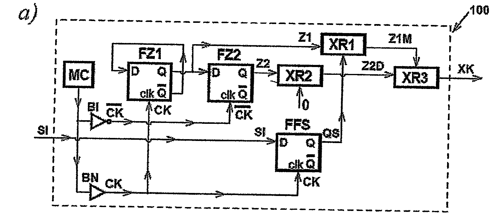
[0083]For example, if the frequency of the master clock MC equals 100 MHz, then the shortest time interval will be either 40 ns (if there is no delay in the pulse train XK) or 45 ns (if a delay step has been introduced into the pulse train XK).

[0084]Similarly, because the greatest value represented by an allowable LFSR state {S*} is


PUM


Abstract

A spread-period clock generator (SPC) counts basic clock pulses (XK) to generate output pulses (EQ) with varying periods, and has means (controlled by signal QS) for switching between a first mode, in which counting is carried out in response to the leading edges of the basic clock pulses (CK), and a second mode, in which counting is carried out in response to the trailing edges of the basic clock pulses (CK). Accordingly, if mode switching (signal QS) is carried out during a counting operation, the counting period is altered by a portion of a basic clock period (CK). Thus, the number of different periods of the output pulses can be increased without increasing the basic clock frequency (input WC, signal LK, CK).

Description

BACKGROUND OF THE INVENTION[0001]1. Field of the Invention[0002]This invention relates to a method and apparatus for generating pulse trains with variable interpulse intervals, for example to be employed to drive suitable waveform generators utilized in multi-user active sensor systems and particularly, but not exclusively, in automotive radar systems designed to perform functions of obstacle-detection and / or collision avoidance.[0003]2. Description of the Prior Art[0004]In a multi-user environment, active sensors may transmit their interrogating signals simultaneously and asynchronously so that not only must each receiver recognize and detect a response to its own transmitted signal, but it must be able to do so in the presence of all other transmitted signals.[0005]For example, in automotive applications, many similar obstacle-detection systems should be capable of operating in the same region, and also be capable of sharing the same frequency band. To avoid mutual interference, e...

Claims


Application Information

Patent Timeline
Patent Type & Authority Applications(United States)
IPC IPC(8): H03L7/00
CPCH03C3/406H03K23/00H03K3/84H03K3/00
Inventor SZAJNOWSKI, WIESLAW JERZY
Owner MITSUBISHI ELECTRIC CORP
Why Eureka
Try Eureka