Reference bias generating circuit

a reference bias and generation circuit technology, applied in the direction of amplifiers with semiconductor devices only, instruments, etc., can solve the problems of not being able to apply circuits using a supply voltage below 1.2v, affecting badly the performance of electronic systems, and increasing power consumption of electronic systems. to achieve the effect of reducing power consumption

Active Publication Date: 2010-06-10
ELECTRONICS & TELECOMM RES INST
View PDF13 Cites 25 Cited by
  • Summary
  • Abstract
  • Description
  • Claims
  • Application Information

AI Technical Summary

Benefits of technology

[0023]Another embodiment of the present invention is directed to

Problems solved by technology

Overall power consumption of an electronic system has increased due to the diversification of applications and the increments of functions to provide to a user.
In a system with various ICs, the incre

Method used


Image

  • Reference bias generating circuit
  • Reference bias generating circuit
  • Reference bias generating circuit

Examples


Embodiment Construction

[0035]The advantages, features and aspects of the invention will become apparent from the following description of the embodiments with reference to the accompanying drawings, which is set forth hereinafter.

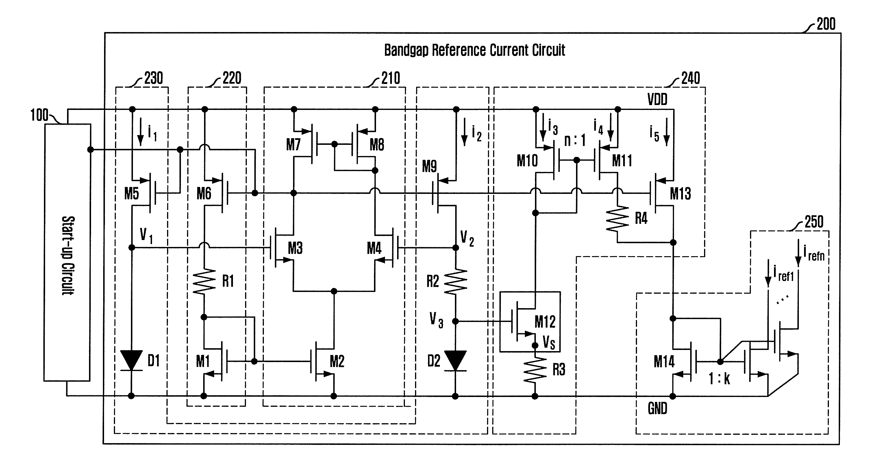
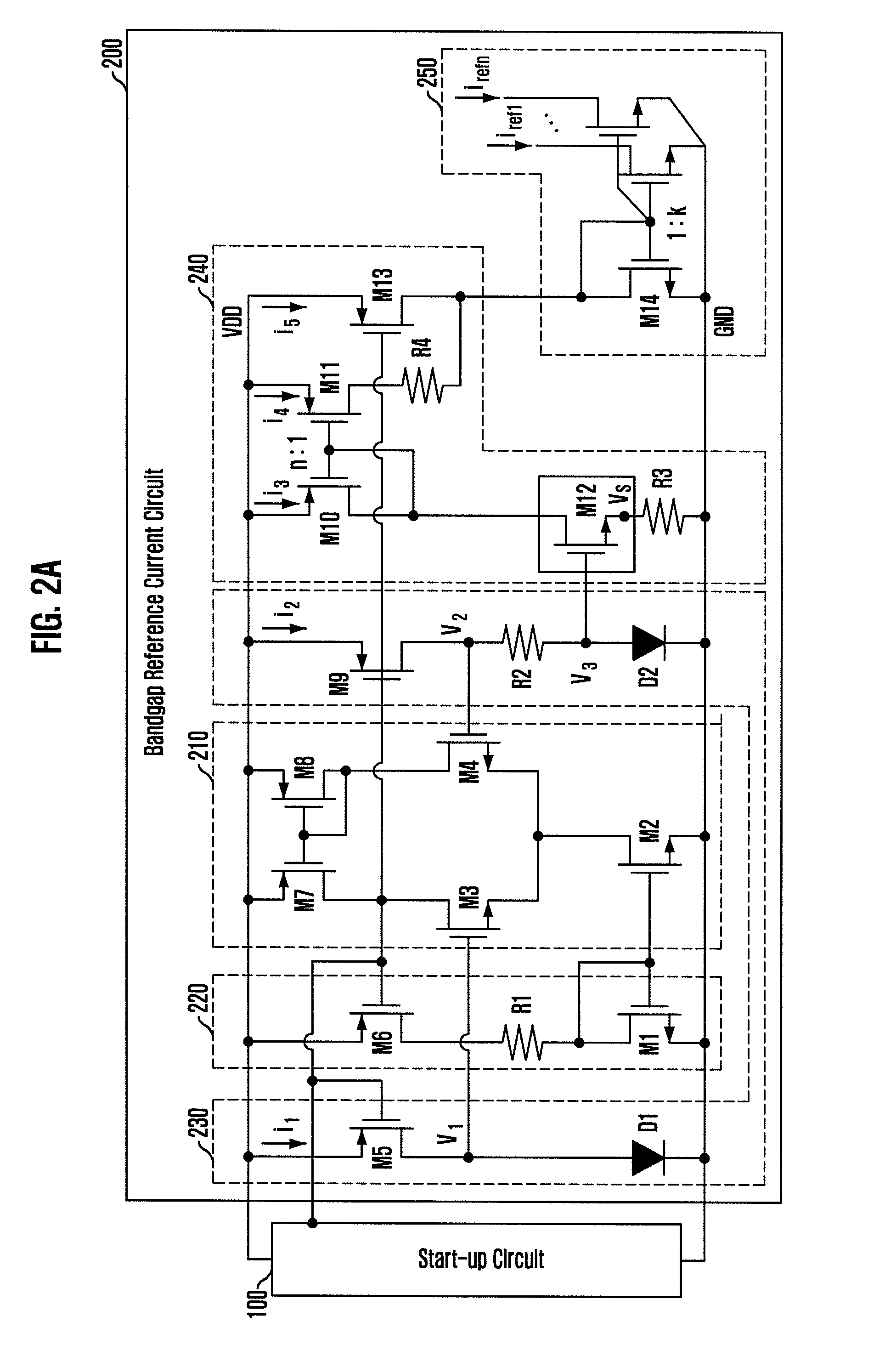
[0036]FIG. 2A is a diagram illustrating a reference current bias circuit for low supply voltage in accordance with an embodiment of the present invention.

[0037]Referring to FIG. 2A, the reference current bias circuit according to the present embodiment includes a start-up circuit 100 and a bandgap reference current circuit 200. The start-up circuit 100 supports an initial operation of the reference current bias circuit to quickly reach a normal state without falling into an abnormal zero state. The bandgap reference current circuit 200 includes an amplifier 210, a self-bias unit 220 for driving the amplifier 210, a basic bandgap unit 230 having two input terminals, a temperature compensator 240 for eliminating a temperature variation characteristic, and a reference current mirror...


PUM


Abstract

A reference current bias circuit includes a self-bias circuit configured to provide a bias current to an amplifier; a basic bandgap circuit coupled to inputs of the amplifier; a startup circuit configured to support an initial operation of the amplifier; a temperature compensator configured to include a first mirroring unit for mirroring current according to a positive temperature coefficient characteristic from the basic bandgap circuit; and a second mirroring unit for mirroring current according to a negative temperature coefficient characteristic from the basic bandgap circuit, and to provide a reference current by combining the current of the first mirroring unit and the current of the second mirroring unit; and a reference current mirroring unit configured to generate reference current biases based on the reference current from the temperature compensator.

Description

CROSS-REFERENCE TO RELATED APPLICATIONS[0001]The present invention claims priority of Korean Patent Application No. 10-2008-0123456, filed on Dec. 5, 2008, which is incorporated herein by reference.BACKGROUND OF THE INVENTION[0002]1. Field of the Invention[0003]The present invention relates to a reference bias generating circuit; and, more particularly, to a low-voltage reference bias generating circuit.[0004]2. Description of Related Art[0005]In general, a circuit of an electronic system is formed in an integrated chip including a plurality of active elements and passive elements. Each of the elements in the electronic system requires a reference bias circuit. The reference bias circuit generates a reference voltage and a reference current for stable operation of the electronic system. Therefore, the bias circuit is an important element in an electronic system.[0006]Overall power consumption of an electronic system has increased due to the diversification of applications and the in...

Claims


Application Information

Patent Timeline
IPC IPC(8): H03F3/04
CPCG05F3/30H03F2200/78H03F2200/447H03F1/301G05F3/20
Inventor KIM, YOUNG-HOYUN, JE-HOON
Owner ELECTRONICS & TELECOMM RES INST
Why Eureka
Try Eureka