Photovoltaic power conditioning system and method

a power conditioning system and photovoltaic technology, applied in photovoltaic energy generation, dc-dc conversion, transportation and packaging, etc., can solve the problems of reducing affecting the efficiency of the system, so as to reduce the required power capacity of the system, reduce the rated current of the inverter, and reduce the capacity of the converter.

Active Publication Date: 2010-06-10
KOREA ELECTROTECH RES INST
View PDF7 Cites 12 Cited by
  • Summary
  • Abstract
  • Description
  • Claims
  • Application Information

AI Technical Summary

Benefits of technology

[0023]The photovoltaic power conditioning system and method according to the present invention significantly reduces a required power capacity of the system using a new DC / DC conversion structure in which a DC input portion is connected in parallel to a conversion input portion and a conversion output portion is connected in series to the DC input portion.
[0024]The system is designed by fully utilizing the power generation characteristics of the solar cell and using the new DC / DC conversion structure, so that the capacity of the converter can be greatly reduced to be below 20% of the rated capacity of the system.
[0025]The same output voltage as the grid voltage can be supplied by increasing the DC voltage, so that the rated current of the inverter can be reduced by half, thereby reducing the price of the components of the inverter and increasing the efficiency of the inverter.
[0026]The efficiency of the system can be significantly increased using the new DC / DC conversion structure and the power generation characteristics of the solar cell.
[0027]Since the capacity of the DC / DC converter is significantly reduced, the DC / DC converter can be applied not only to a small capacity system but also to a large capacity system.

Problems solved by technology

However, the system of FIG. 1 is big and heavy since it uses the low frequency transformer 13.
This leads to an increase in the costs of the components and a reduction in the efficiency of the system.
However, the topology of FIG. 2 has the following problem.
However, the efficiency of the converter is generally lower than the low frequency transformer, so that the efficiency of the system is lower than that of FIG. 1.
However, the topology of FIG. 3 has the same problem as that of FIG. 2.
In the exemplary topology of FIG. 1, the capacity of the converter must be equal to that of the system since it does not fully utilize the output characteristics of the solar cell, thereby reducing the efficiency of the system.

Method used


Image

  • Photovoltaic power conditioning system and method
  • Photovoltaic power conditioning system and method
  • Photovoltaic power conditioning system and method

Examples


Embodiment Construction

[0040]Embodiments of a photovoltaic power conditioning system and method according to the present invention will now be described in detail with reference to the accompanying drawings.

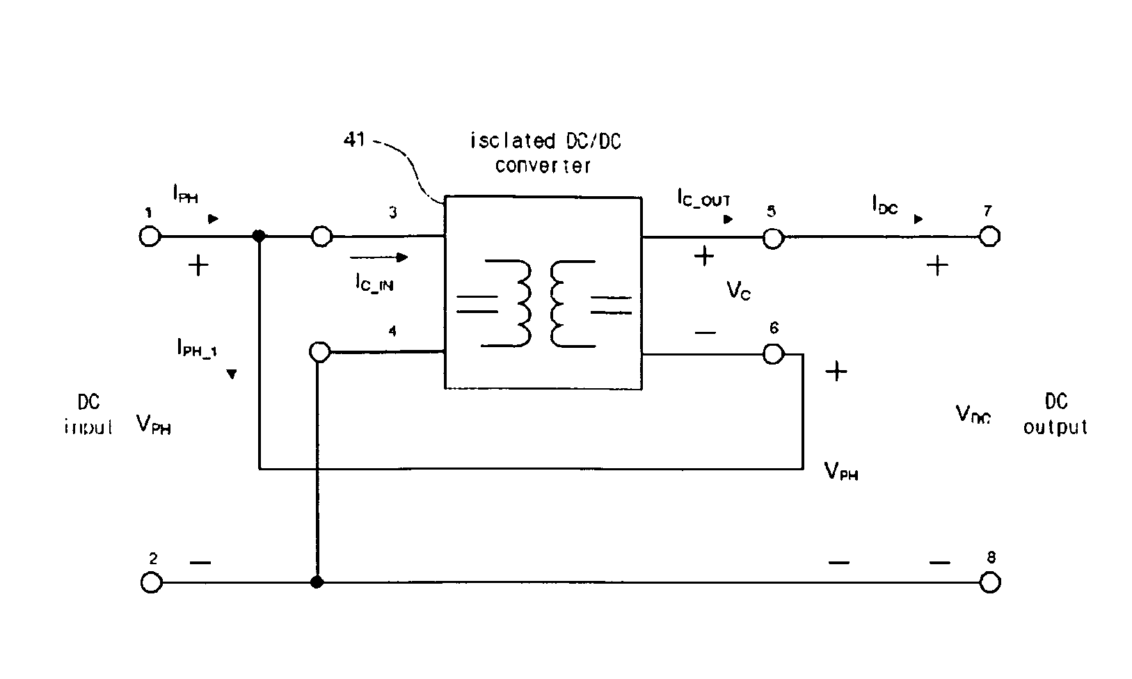
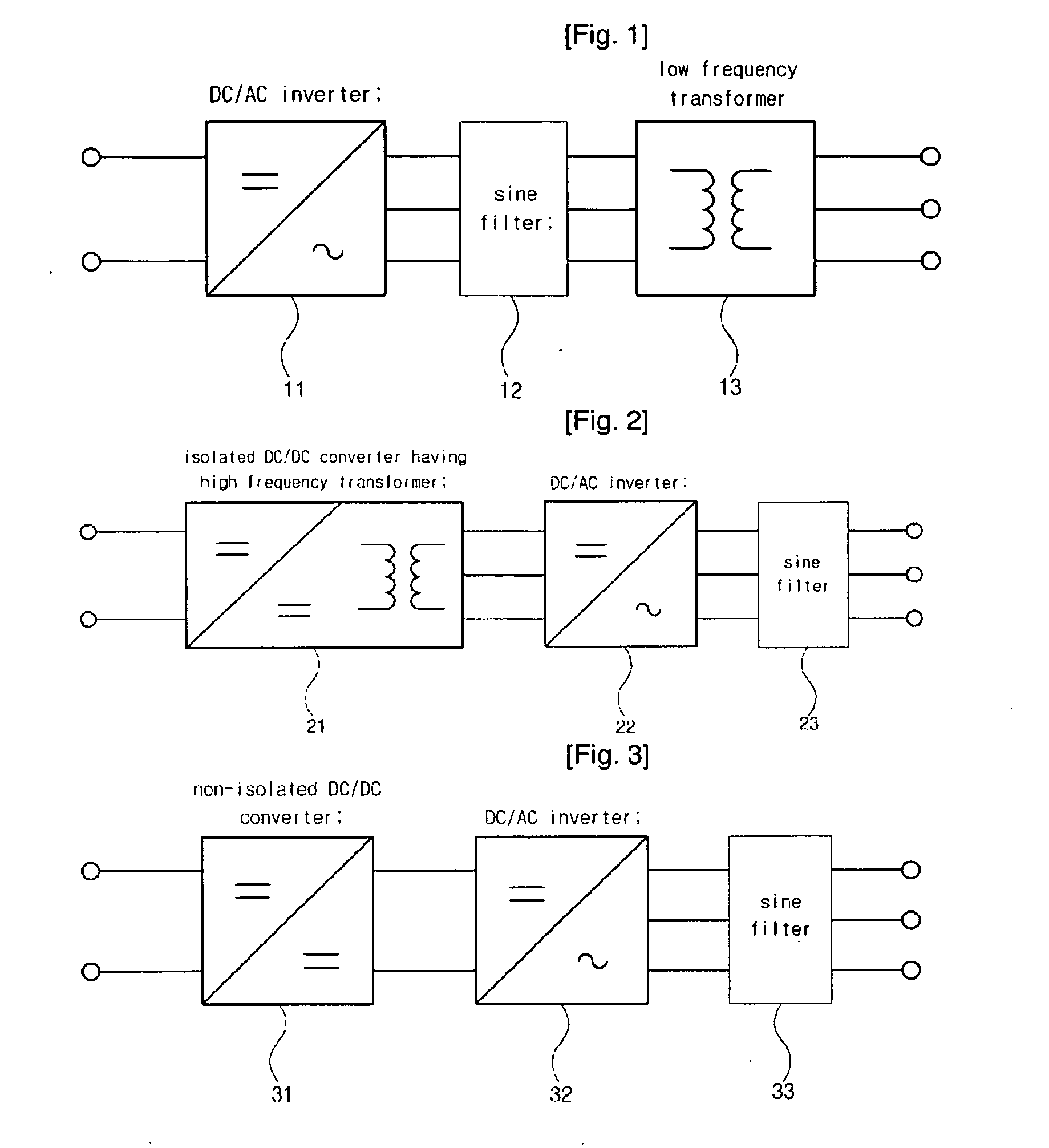
[0041]The photovoltaic power conditioning system according to the present invention employs a topology allowing the system to be responsible for part of the output capacity, thereby significantly reducing the required capacity and increasing the system efficiency, so that the system can be applied to small and large-capacity photovoltaic power generation.

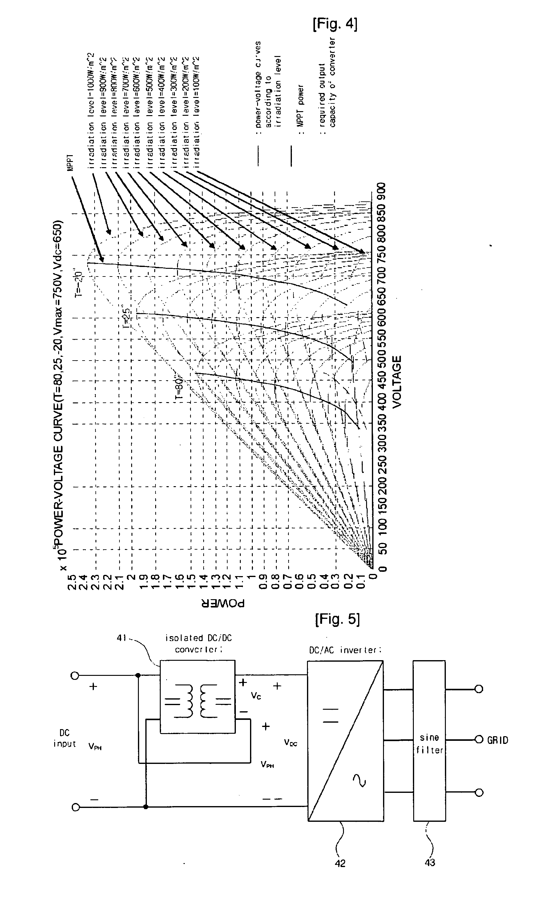
[0042]FIG. 4 is a graph showing characteristic curves of a general solar cell according to temperature and irradiation level.

[0043]The solar cell can be modeled by Equations 1 to 3.

I=ILG-Ios{exp[qAkTK(V+IRs)]-1}-V+IRsRsh<MathFigure1>Ios=Ior(TKTr)3exp[qEGOBk(1Tr-1TK)]<MathFigure2>ILG=ISC-KI(T-25)λ1000<MathFigure3>

[0044]The following are the definitions of symbols in Equations 1 to 3.

[0045]IOS: cell reverse saturation current

[0046]T: ce...


PUM


Abstract

A photovoltaic power conditioning system and method is provided. The system includes an isolated DC / DC converter (41), a DC / AC inverter (42), and a sine filter (43). The isolated DC / DC converter (41) receives a DC voltage from a solar cell through a parallel connection structure and converts the DC voltage into another DC voltage and then outputs the converted DC voltage through a series connection structure. The DC / AC inverter (42) converts the DC voltage output from the isolated DC / DC converter into an AC voltage. The sine filter (43) performs sine filtering on the AC voltage output from the DC / AC inverter and outputs the filtered AC voltage. The system employs a topology allowing it to be responsible for part of the output capacity, thereby significantly reducing the required capacity and increasing the system efficiency, so that the system can be applied to small and large-capacity photovoltaic power generation.

Description

TECHNICAL FIELD[0001]The present invention relates to a photovoltaic Power Conditioning System (PCS), and more particularly to a photovoltaic power conditioning system and method which employs a topology allowing the system to be responsible for part of the output capacity, thereby significantly reducing the required capacity and increasing the system efficiency, so that the system is suitable for application to small and large-capacity photovoltaic power generation.BACKGROUND ART[0002]Photovoltaic power generation (also referred to as “photovoltaics”) is a technology for generating electricity from solar energy. This technology directly converts solar energy into electric energy using a photoelectric converter that is referred to as a “solar cell”. Since the photovoltaic power generation can use limited amounts of light, it can also be used in cloudy weather and its utilization is higher than that of thermal power generation.[0003]A variety of methods have been employed to achieve ...

Claims


Application Information

Patent Timeline
Patent Type & Authority Applications(United States)
IPC IPC(8): H02M7/00
CPCY10S323/906H02J3/38H02M1/0093Y02E10/56H02J7/35H02M3/155
Inventor MIN, BYUNG DUKYOO, DONG WOOKBAK, JU WONKIM, TAE JINKIM, JONG HYUNRYU, MYUNG HYOLEE, JONG PIL
Owner KOREA ELECTROTECH RES INST
Why Eureka
Try Eureka