Compressor stabilizer

Inactive Publication Date: 2010-06-10
ABB TURBO SYST
View PDF7 Cites 22 Cited by
  • Summary
  • Abstract
  • Description
  • Claims
  • Application Information

AI Technical Summary

Problems solved by technology

Recirculation therefore no longer takes place, which results in the desired displacement of the surge limit toward higher throughputs.
The desired expansion of the characteristic map of the compressor often comes at the expense not only of efficiency losses but als

Method used


Image

  • Compressor stabilizer
  • Compressor stabilizer

Examples


Example

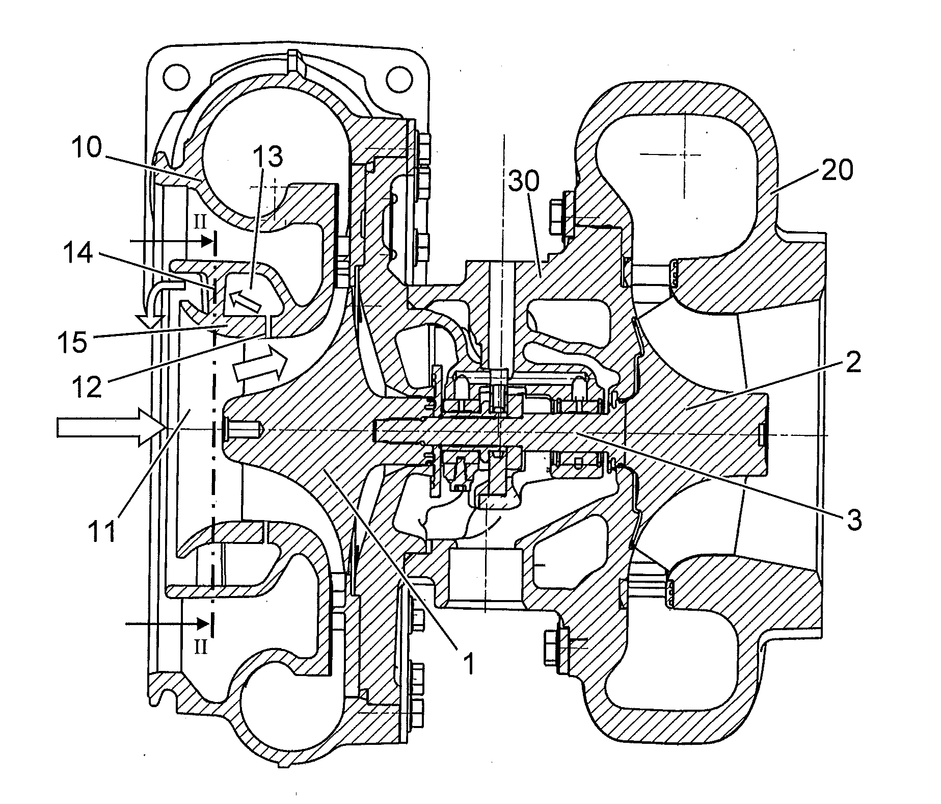
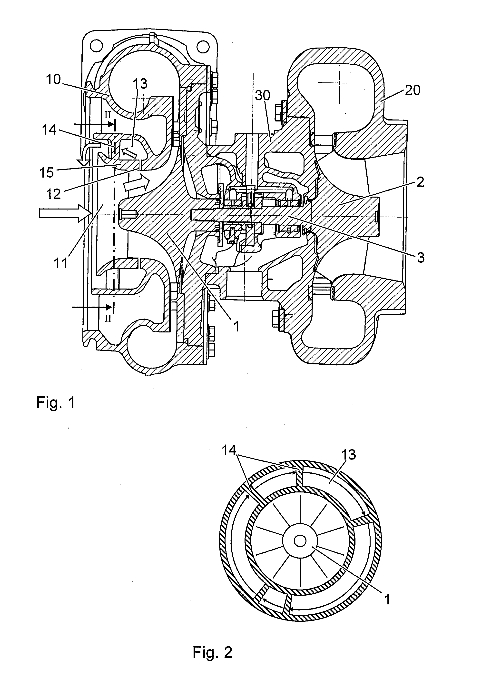
[0013]Vibration-reducing measures are disclosed for a compressor having a circulation chamber which is delimited from the main flow.

[0014]According to the exemplary embodiments, the struts which support a contoured wall are arranged spaced apart from one another to different extents in a circumferential direction.

[0015]A uniform distribution of support ribs can lead to formation of exemplary excitation orders in the vibration excitation, with the excitation orders being directly dependent on the number of support ribs. With a non-uniform distribution, the available excitation energy can be distributed between different excitation orders. The excitation per excitation order can therefore be reduced, and specific resonances can be targeted and avoided (e.g., suppressed). A non-uniform distribution of the support ribs can therefore lead to a reduced excitation of the rotor blade vibration.

[0016]The non-uniform distribution of the support ribs can have an effect on distribution of the c...


PUM


Abstract

An annular circulation chamber is arranged in an interior of a compressor housing, which circulation chamber radially surrounds a main flow duct and extends from an intake region to an encircling circulation opening in a region of rotor blades of the compressor wheel. Between the circulation openings, the circulation chamber is delimited from the main flow duct by an annular contoured wall. The contoured wall is connected to the inner compressor housing by plural struts which are spaced apart from one another to different extents in the circumferential direction. As a result of the irregular distribution of the struts in the circumferential direction, generation of undesired vibration excitations can be reduced and/or eliminated.

Description

RELATED APPLICATION[0001]This application claims priority under 35 U.S.C. §119 to European Patent Application No. 08170848.9 filed in Europe on Dec. 5, 2008, the entire content of which is hereby incorporated by reference in its entirety.FIELD[0002]The disclosure relates to the field of exhaust-gas-driven turbochargers, which, for example, include a compressor having a circulation chamber which is delimited from a main flow.BACKGROUND INFORMATION[0003]To increase the power of an internal combustion engine, it is known to use exhaust-gas turbochargers having a turbine in the exhaust section of the internal combustion engine and having a compressor which is positioned upstream of the internal combustion engine. Here, the exhaust gases of the internal combustion engine are expanded in the turbine. The work which is gained here is transmitted by a shaft to the compressor which compresses the air supplied to the internal combustion engine. By using the energy of the exhaust gases to comp...

Claims


Application Information

Patent Timeline
IPC IPC(8): F01D9/00
CPCF02C6/12F04D27/0207F05D2260/96F04D29/665F04D29/4213F04D29/685F05D2220/40F02B39/00F04D29/52
Inventor KUEHNEL, JANPETER
Owner ABB TURBO SYST
Why Eureka
Try Eureka