Energy Absorption Material

a technology of energy absorption and energy absorption materials, which is applied in the direction of vehicle safety arrangements, synthetic resin layered products, packaging, etc., can solve the problems of affecting the aerodynamics of vehicles, requiring substantial development time and engineering effort, and known energy absorption materials that do not provide effective and economic pedestrian impact energy absorption, etc., to achieve excellent impact energy management capability, effectively cushion impact and convert impact energy

Inactive Publication Date: 2010-06-10
WARRICK RUSSELL C
View PDF7 Cites 28 Cited by
  • Summary
  • Abstract
  • Description
  • Claims
  • Application Information

AI Technical Summary

Benefits of technology

[0008]The novel energy absorption material disclosed herein achieves excellent impact energy management capability due to sequential compression, buckling, and even failure of interleaved layers of the constituent materials. The constituent materials include, for example, a thermoplastic nylon foam from Zotefoams, Zotek-N B50, along with a thermoset epoxy resin prepregged onto woven fiberglass, made by Cytec Engineered Materials of Anaheim, Calif., USA. With this combination of materials, the foam compresses and cushions impacts while the fiberglass and epoxy material buckles and fails while spreading the impact load over a larger area to more effectively cushion an impact and convert impact energy into other forms of energy. Interleaving of materials causes the structural fiberglass and epoxy material to hold the compressible foam in shape after molding. The structural interleaved layers resists flexing and bending of the material substantially because shear loads in the foam are transferred to the structural fiberglass and epoxy layers adjacent to the foam layers.
[0010]Utilized this novel material for a vehicle hood is analogous to making the hood out of bike-helmet-like material. Material thickness is easily varied by adding additional interleaved layers of material in desired locations to conform to under-hood components. Any dead space between the hood skin and engine bay hard points can be filled with this material to cushion impacts to the underlying structures. The material doesn't need to deform as most prior art metal pedestrian protection hoods which bend over a large area and convert impact energy through deforming the metal. Rather, the novel material disclosed herein fails locally, transverse to the plane of the interleaved material. The thicker the material is, the more cushioning and energy conversion and energy storage capability the material has.
[0011]Filling the space between under hood hard points and the vehicle exterior with the novel material disclosed herein is one option for improving the pedestrian protection performance in these areas. Filling the space between under hood hard points and the vehicle exterior with the novel material disclosed herein also helps prevent large scale bending of the hood material as occurs with prior art materials. a Such large scale bending as occurs with prior art materials is a less effective energy conversion mechanism than locally compressing and failing the material with the desired transverse compression energy conversion mechanisms of the novel interleaved materials disclosed herein. The interleaved nature of this novel material also helps resist sharp objects from poking or cutting through the material as easily as in a single-layer materials as are known in the prior art because the interleaved layers of the disclosed material help reinforce the material.
[0012]The novel material disclosed herein eliminates the need in the prior art for space-intensive active hood systems and by minimizes the space required for deformation of the hood through the use of a very space-efficient energy conversion material. Accordingly, aerodynamic performance and various critical design aesthetics which are characteristic of a traditional low hood are preserved. The highly space and weight efficient cushioning effect of the novel material disclosed herein permits optimization of under hood components, hard points and overall packaging for mechanical purposes, weight distribution, cooling, other performance issues, cost, aesthetic design considerations, and other commercial or practical reasons.
[0014]Other benefits of the novel material system disclosed herein include: reduced bonnet or hood weight, adaptability to virtually all under-bonnet or hood hard points, closer packaging of hood and under-hood components, optimized placement and packaging of under-hood components, improved sound damping, improved thermal insulation, and co-molded features for integration of systems such as photovoltaics in hood or roof panels. Significantly reduced tooling investment and tooling production lead time are two secondary benefits of this technology.

Problems solved by technology

However, known energy absorption materials do not provide effective and economic pedestrian impact energy absorption for car hoods and fenders and other vehicle components, as well as other applications which are detailed herein.
Unfortunately, higher hoods typically adversely affect the aerodynamics of the vehicle and also detract from certain design aesthetics such as a low hood, which is typically regarded as a desirable design feature for many vehicles including sedans, coupes, and sports-oriented vehicles.
One drawback of known active systems is that they are typically very expensive and heavy and require substantial development time and engineering effort.
These systems often require thicker, stiffer, load-bearing skins, and either do not substantially utilize the compressible material to contribute to mechanical properties of the hood or other component, or the systems have to compensate for their inherent lack of flexural stiffness by utilizing stiffer skins to provide structure to the hood or other component.
Also, transverse compression of the material often requires greater impact energy to initiate material failure or compression of the skin material, followed by a region of lower resistance to compression during the compression of the compressible material.
This results in higher peak loads in known systems when the skin fails, followed by a less-efficient conversion of impact energy when the compressible material begins to convert impact energy.

Method used


Image

  • Energy Absorption Material
  • Energy Absorption Material
  • Energy Absorption Material

Examples


Embodiment Construction

[0038]In the Figures, like numerals indicate like elements.

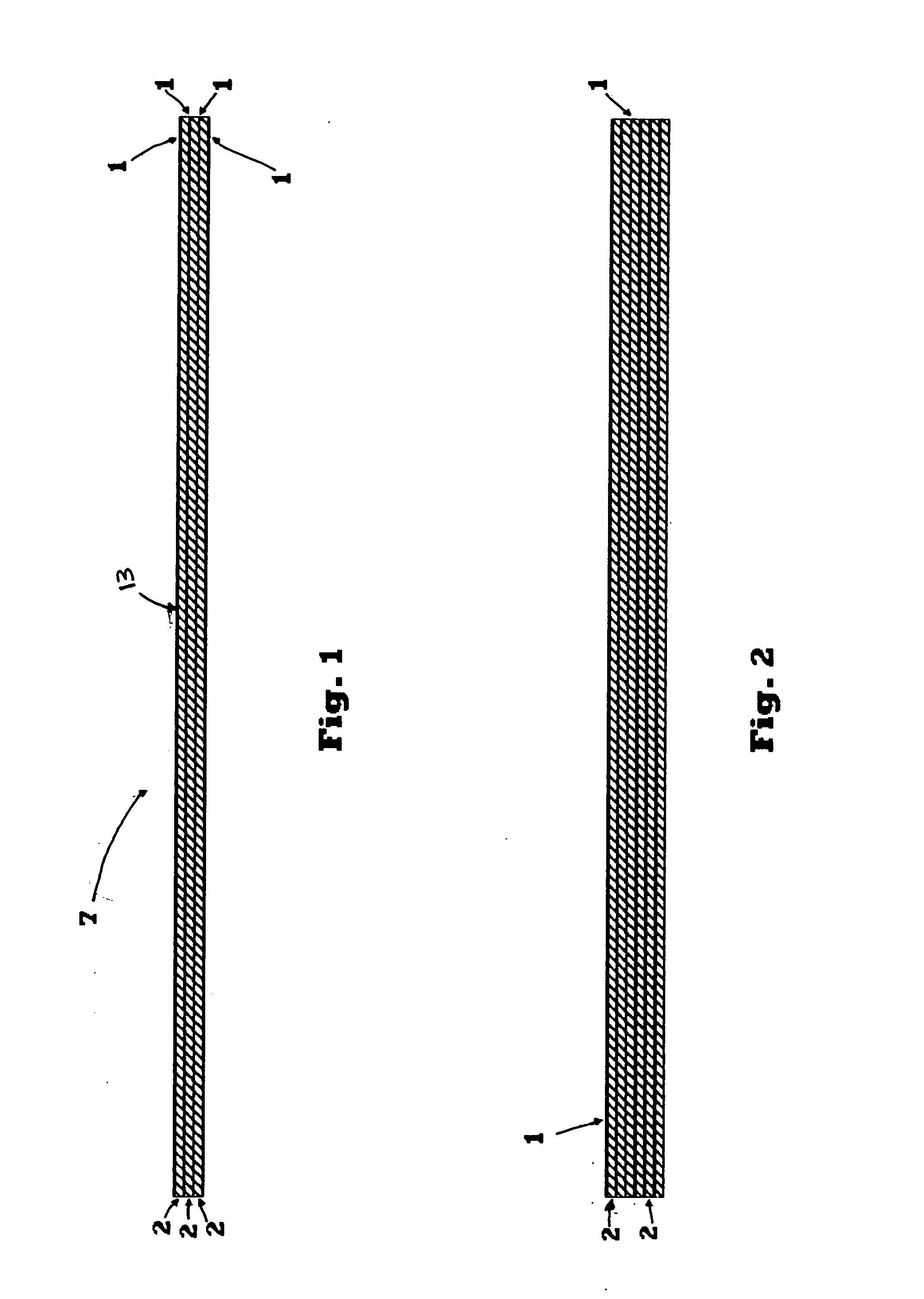
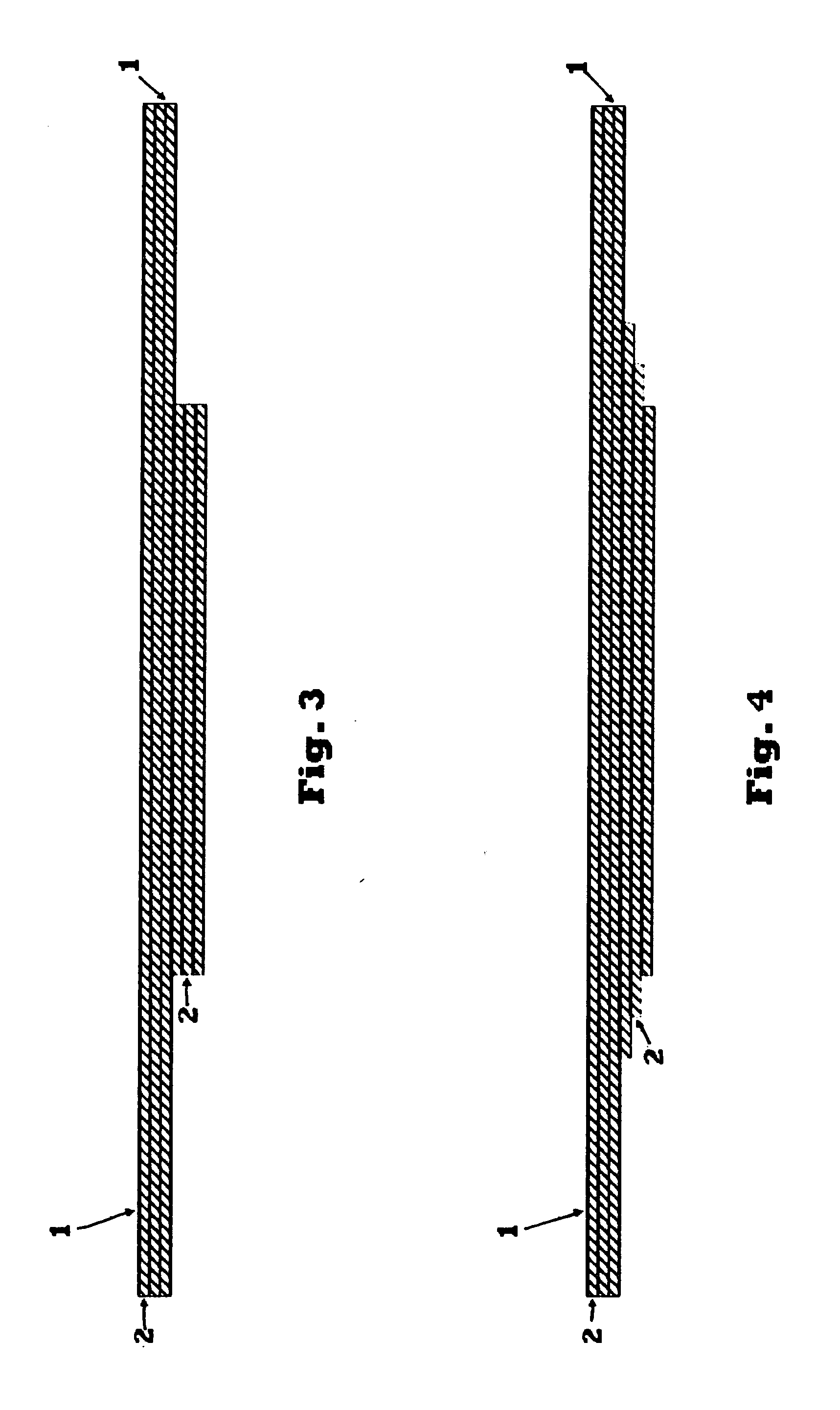
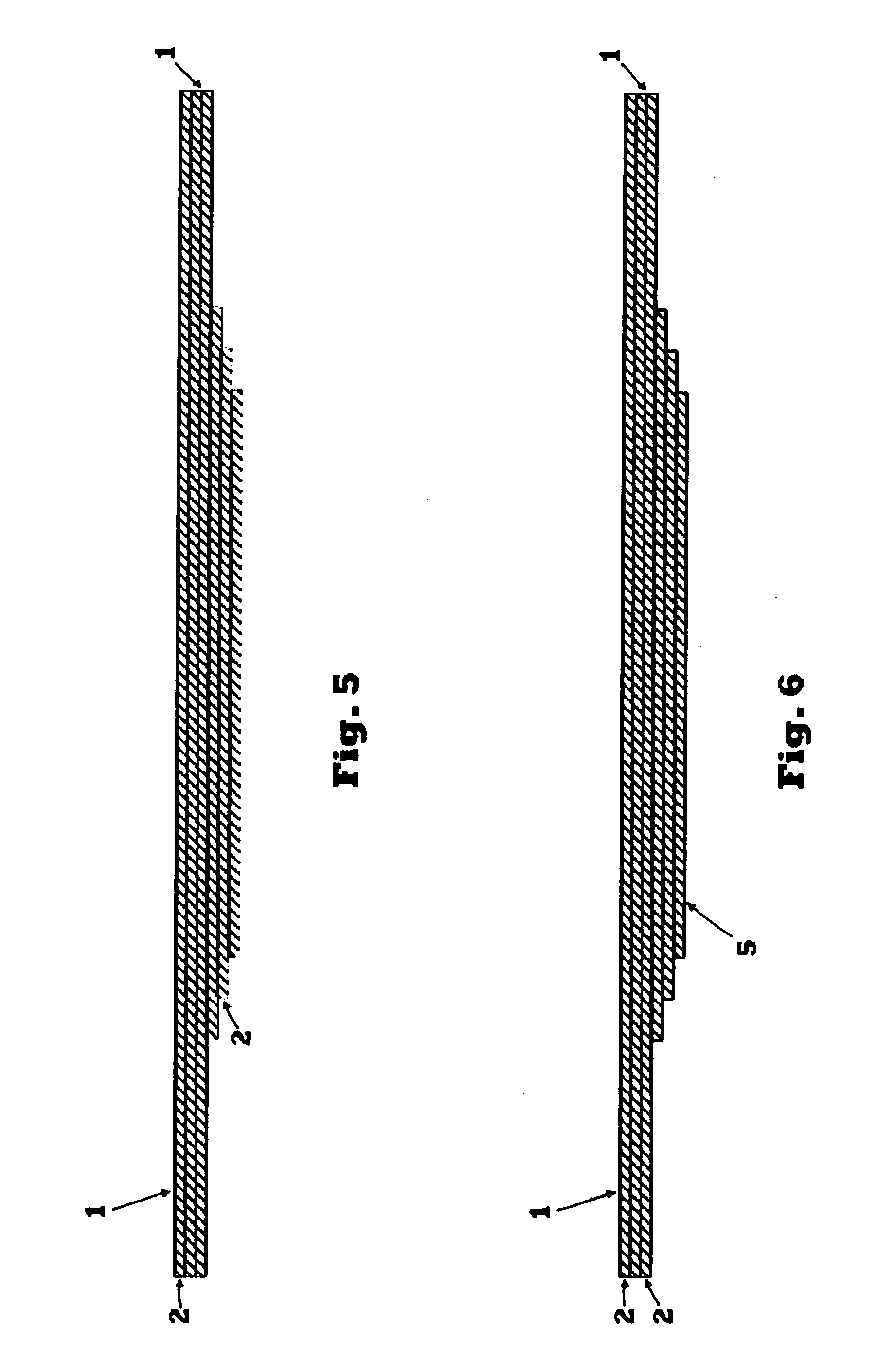
[0039]An energy absorption material 7 and associated configurations, processes and application approaches are disclosed for, though not limited to pedestrian impact energy absorption for vehicle hoods and fenders, as well as other applications which are disclosed herein.

[0040]The energy absorption material 7, shown in FIG. 1, is a plurality of thin structural layers of a substantially rigid material 1 with cushioning layers of a compressible material 2 alternating between the thin structural layers of material 1. According to one embodiment, constituent materials include a thermoplastic nylon foam with a thermoset epoxy resin prepregged onto woven fiberglass. For example, the thermoplastic nylon foam for the layers of compressible material 2 is a type of foam Zotek-N B50 available from Zotefoams, of Croydon, Surrey, UK and Walton, Ky., USA, and one example of the thermoset epoxy resin prepreg with fiberglass reinforcement fo...


PUM

PropertyMeasurementUnit
thicknessaaaaaaaaaa
thicknessaaaaaaaaaa
thicknessaaaaaaaaaa

Abstract

An energy absorption material, formed of a plurality of structural layers each formed of a substantially rigid material; a plurality of cushion layers interleaved with the structural layers, with each cushion layer formed of a substantially compressible material; wherein the cushion layers are coupled to adjacent structural layers; and one of the cushion layers and the structural layers is further positioned on a threat face of the energy absorption material.

Description

FIELD OF THE INVENTION[0001]The present invention relates generally to energy absorption material, and in particular to interleaved materials for pedestrian impact energy absorption for pedestrian protection, wherein hoods and fenders, as well as other vehicle components, are at least partially formed of the energy absorption material.BACKGROUND OF THE INVENTION[0002]Energy absorption materials are generally well-known. However, known energy absorption materials do not provide effective and economic pedestrian impact energy absorption for car hoods and fenders and other vehicle components, as well as other applications which are detailed herein.[0003]Effective impact energy management is necessary for limiting peak acceleration and impact force duration in the human brain and body. Acceleration forces due to an impact along with the duration of the impact are used to calculate Head Impact Criterion (HIC) values which indicate the amount of energy and thus, damage, imparted to the br...

Claims


Application Information

Patent Timeline
Patent Type & Authority Applications(United States)
IPC IPC(8): B32B27/34B32B1/00B32B27/38B32B3/26B32B37/00B32B7/022
CPCB32B5/18Y10T156/10B32B5/28B32B5/32B32B7/02B32B17/04B32B27/04B32B27/12B32B27/34B32B27/38B60R21/34B60R2021/343F16F1/40Y10T428/24628B32B5/26B32B5/024B32B5/026B32B15/04B32B23/04B32B27/20B32B3/08B32B3/12B32B2255/20B32B2255/205B32B2260/046B32B2262/0269B32B2262/101B32B2262/106B32B2266/025B32B2266/0257B32B2266/0264B32B2307/102B32B2307/304B32B2307/558B32B2307/56B32B2605/00Y10T428/31725Y10T428/31511Y10T428/249953B32B7/022F16F7/10B62D25/10B62D27/00
Inventor WARRICK, RUSSELL C.
Owner WARRICK RUSSELL C
Why Eureka
Try Eureka