Battery Pack

a battery pack and battery technology, applied in the field of batteries, can solve the problems of time and labor consumption for battery pack manufacturing, insufficient strength of the upper surface of the battery pack in contact with the positioning member or the like, and so as to reduce the chance of battery pack varying every time, the accuracy of the vertical dimension of the battery pack after the molding of the resin mold can be maintained high, and the reliability of battery pack manufacturing can be increased.

Inactive Publication Date: 2010-06-10
HITACHI MAXELL ENERGY LTD
View PDF8 Cites 31 Cited by
  • Summary
  • Abstract
  • Description
  • Claims
  • Application Information

AI Technical Summary

Benefits of technology

[0016]According to the battery pack of the present invention, the upper cover is pushed by, for example, the inner surface of a metal mold when an intermediary assembly of the battery pack is placed in the metal mold for the molding of the resin mold, the lower end of the positioning projection is brought in contact with the upper surface of the unit cell, and the spacing between the upper cover and the upper surface of the unit cell is regulated to a prescribed spacing. Therefore, a gap for injecting a molten resin in between the upper cover and the upper surface of the unit cell is reliably secured, and the electrical equipments such as lead wires, the PTC element, the circuit board and so on placed between the upper cover and the unit cell can be prevented from coming in contact with one another possibly caused by excessive mutual adjacency.
[0017]The spacing between the upper cover and the upper surface of the unit cell is regulated by the positioning projection and has a reduced chance of its varying every battery pack. Therefore, the accuracy of the vertical dimension of the battery pack after the molding of the resin mold can be maintained high, so that the reliability of manufacturing of the battery pack can be increased. This obviates the need for fixing the upper cover to the upper surface of the unit cell by means of a rivet or the like for the regulation of the spacing between the upper cover and the upper surface of the unit cell and allows the time and labor for manufacturing the battery pack to be reduced by that much.
[0018]Providing the anchor means for the upper cover prevents the upper cover from coming off the resin mold after the molding of the resin mold and from moving toward the upper side of the unit cell. The accuracy of the vertical dimension of the battery pack can be maintained high even in this point, and the reliability of manufacturing of the battery pack can be improved.
[0019]By fitting the circuit board in the board fitting portions provided for the upper cover with no gap, the molten resin does not flow around the upper surface of the circuit board during the molding of the resin mold, and the external connection terminal located on the upper surface of the circuit board can be prevented from being covered with the resin mold. On the

Problems solved by technology

In this case, according to the technique of covering the upper side of the circuit board with a resin mold as shown in JP 2003-17022 A, the strength of the upper surface of the battery pack in contact with the positioning member or the like is insufficient.
However, since the whole body

Method used


Image

  • Battery Pack
  • Battery Pack
  • Battery Pack

Examples


first embodiment

The First Embodiment

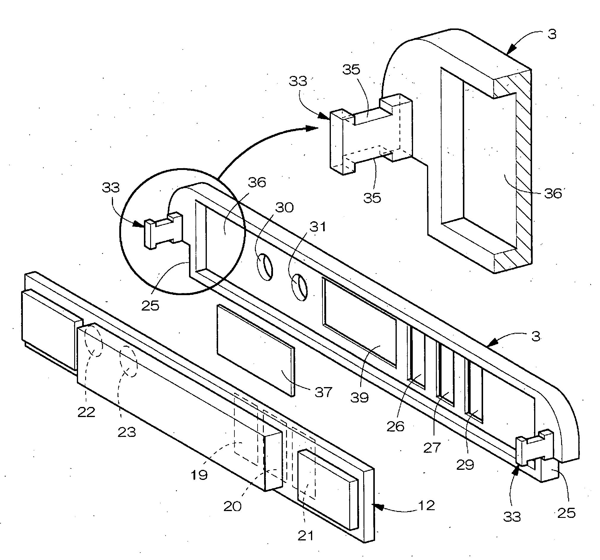
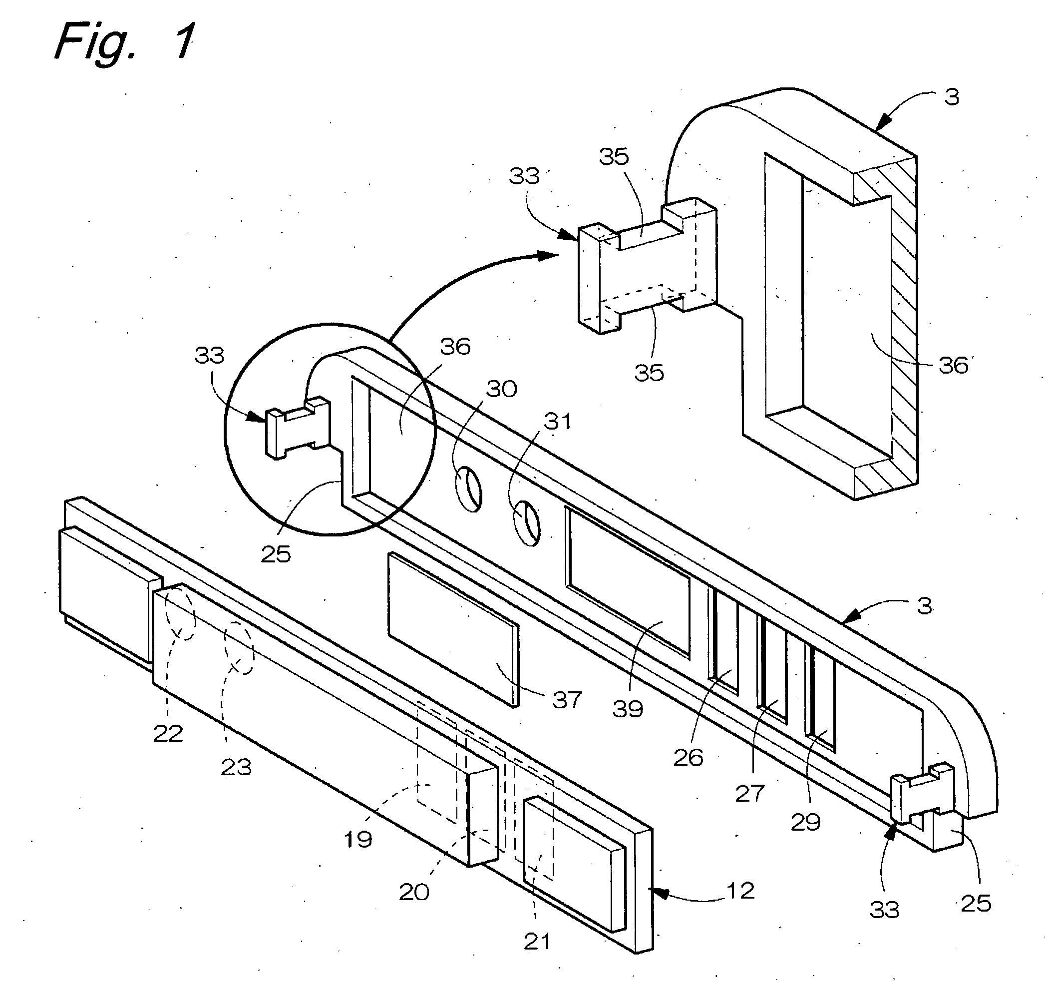
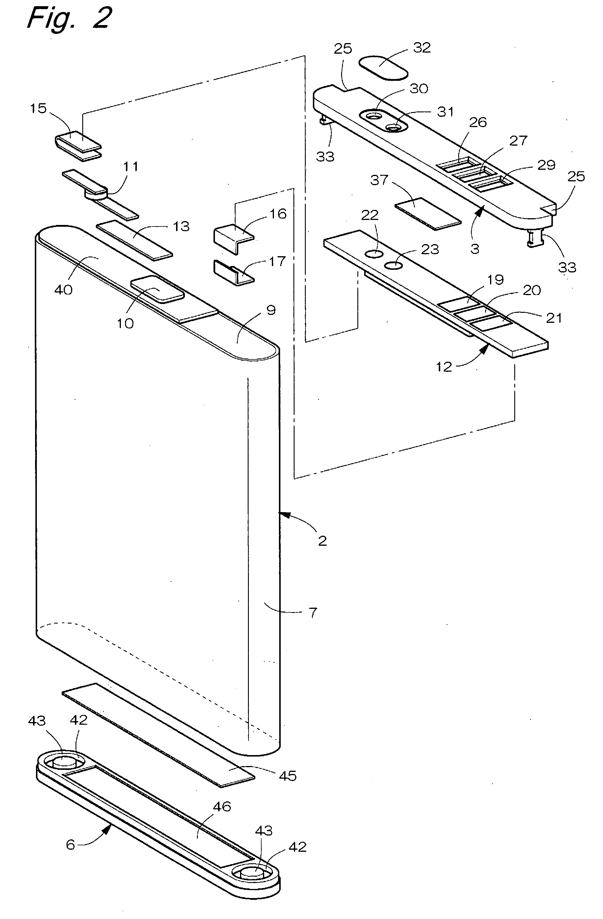
[0034]FIGS. 1 through 6 show the first embodiment of the battery pack of the present invention. As shown in FIGS. 2 and 3, the battery pack 1 of the present invention includes a flat prismatic box shaped unit cell 2, electrical components placed on the upper side of the unit cell 2, a plastic upper cover 3 placed on the upper side of the electrical components, a resin mold 5 that integrates the electrical components with the upper cover 3 on the upper surface of the unit cell 2, and a plastic lower cover 6 fixed to the lower surface of the unit cell 2. The unit cell 2 has, for example, a lateral width dimension of 33.8 mm, a vertical height dimension of 46 mm and a depthwise thickness dimension of 44.5 mm.

[0035]The resin mold 5 is formed of, for example, a polyamide based resin or a polyester based resin and insulates and protects the electrical components from the outside. As shown in FIG. 2, the unit cell 2 has a depthwise thickness dimension smaller than the v...

second embodiment

The Second Embodiment

[0051]In the second embodiment, plate-shaped anchor portions 49, 49 are provided as anchor means projecting downward at the front and rear edges (upper and lower positions in FIG. 7) laterally in the middle of the lower surface of the upper cover 3 as shown in FIG. 7 instead of the formation of the positioning recess portions 35, 35 at the positioning projections 33 of the upper cover 3.

[0052]Three through holes 50 through which the molten resin of the resin mold 5 passes are arranged laterally side by side penetrating the side surfaces of the anchor portions 49. The anchor portions 49 have a vertical dimension smaller than the vertical dimension of the positioning projections 33, so that the spacing regulation by the positioning projections 33 is not obstructed. Since the other points are the same as those of the first embodiment, no description is provided therefor.

[0053]In the second embodiment, by making the resin mold 5 enter the through holes 50 of the anc...

third embodiment

The Third Embodiment

[0054]In the third embodiment, engagement portions 51 are provided projecting downward to the right-hand and left-hand ends at the front and rear edges of the upper cover 3 as shown in FIG. 9 in place of the double-faced tape 37 and the tape fitting portion 39 for sticking the upper cover 3 to the circuit board 12.

[0055]As shown in FIG. 10, the engagement portions 51 are formed in a hook-like shape overlapping the board fitting portion 36 and fixes the upper cover 3 to the circuit board 12 in an engagement manner by the engagement portions 51. That is, by pressurizing the lower surface side of the upper cover 3 against the circuit board 12, the circuit board 12 fits in the board fitting portion 36 pushing aside the engagement portions 51. Then, the engagement portions 51 are restored into the state of FIG. 10 to hook the lower surface of the circuit board 12, by which the upper cover 3 is fixed to the circuit board 12.

[0056]It is noted that the engagement portion...


PUM


Abstract

The battery pack of the present invention includes a circuit board placed on the upper side of a unit cell, an upper cover placed on the upper side of the circuit board, and a resin mold that is formed in between the upper cover and the upper surface of the unit cell and integrates the circuit board and the upper cover with the upper surface of the unit cell. External connection terminals for connection with the contact terminals of external equipment are placed on the upper surface of the circuit board, and the upper cover has a window that is provided in a penetrating form facing the external connection terminals. In order to regulate a spacing between the upper cover and the upper surface of the unit cell, a positioning projection is provided directed downward at both right and left ends on the lower surface of the upper cover, and a board fitting portion in which the circuit board is fit is formed on the lower surface of the upper cover.

Description

BACKGROUND OF THE INVENTION[0001]The present invention relates to a battery pack in which a circuit board is placed on the upper side of a unit cell, and an upper cover is placed on the upper side of the circuit board, the circuit board and the upper cover being integrated with each other on the upper surface of the unit cell with a resin mold.[0002]In JP 2004-221026 A (see particularly FIGS. 1 and 5) and JP 2003-17022 A (see particularly FIGS. 3 and 4), external connection terminals are placed on the upper surface of a circuit board, and the circuit board and so on are integrated with a unit cell with a resin mold in a state in which the external connection terminals are exposed on the upper surface of the battery pack.[0003]Moreover, JP 2003-308881 A (see particularly FIG. 1) and JP 2004-335387 A (see particularly FIGS. 1 through 3) each discloses a battery pack in which the upper cover, the circuit board and so on are placed on the upper side of the unit cell. Furthermore, in JP ...

Claims


Application Information

Patent Timeline
IPC IPC(8): H01M2/04H01M50/202H01M50/278H01M50/287H01M50/296
CPCH01M6/42H01M2/1022H01M50/278H01M50/202H01M50/296H01M50/287Y02E60/10
Inventor YAMAMOTO, HIROSHI
Owner HITACHI MAXELL ENERGY LTD
Why Eureka
Try Eureka