Managing and monitoring emergency services sector resources

a technology for emergency services and resources, applied in transmission, data processing applications, instruments, etc., can solve the problems of poor wireless security, limited system utilizing rfid tags, poor scalability, etc., and achieve the effect of minimizing congestion, maximizing network range, and minimizing rf pollution

Inactive Publication Date: 2010-06-10
GOOGLE LLC
View PDF18 Cites 75 Cited by
  • Summary
  • Abstract
  • Description
  • Claims
  • Application Information

AI Technical Summary

Benefits of technology

[0074]Another aspect of the present invention relates to a method of accommodating large numbers of simultaneous attempts for network access by dynamic “pacing” of network operation, wherein if large numbers of nodes attempt to access a network simultaneously, the method applies timers and random back-offs to minimize congestion.
[0075]Another aspect of the present invention relates to a method for minimizing RF pollution (the total number of transmissions) and battery conservation while maximizing network range, including using network nodes to repeat a network beacon in a semi-random way wherein networks announce their availability with a beaco...

Problems solved by technology

Further, confusion often results when several tagged assets are in close proximity.
Moreover, it will be appreciated that systems utilizing RFID tags are limited by poor scalability, poor wireless security, RF noise and interference, lack of real-time alerting, poor ability to adjust to changes in number and configuration of tagged assets, poor sensor integration capability, and high infrastructure requirements.
Systems utilizing GPS generally are no more ideal, as GPS requires line-of-sight reception from multiple satellites, which limits system utility with assets that are located indoors or in other obscured sites.
Indeed, it will be appreciated that systems utilizing GPS are limited by its high consumption of battery power, high device costs, high operating costs, and need for a separate data communications link to report asset position and/or to report sensor data.
It will still further be appreciated that de...

Method used


Image

  • Managing and monitoring emergency services sector resources
  • Managing and monitoring emergency services sector resources
  • Managing and monitoring emergency services sector resources

Examples


Embodiment Construction

[0138]As a preliminary matter, it will readily be understood by one having ordinary skill in the relevant art (“Ordinary Artisan”) that the present invention has broad utility and application. Furthermore, any embodiment discussed and identified as being “preferred” is considered to be part of a best mode contemplated for carrying out the present invention. Other embodiments also may be discussed for additional illustrative purposes in providing a full and enabling disclosure of the present invention. As should be understood, any embodiment may incorporate only one or a plurality of the above-disclosed aspects of the invention and may further incorporate only one or a plurality of the above-disclosed features. Moreover, many embodiments, such as adaptations, variations, modifications, and equivalent arrangements, will be implicitly disclosed by the embodiments described herein and fall within the scope of the present invention.

[0139]Accordingly, while the present invention is descri...


PUM


Abstract

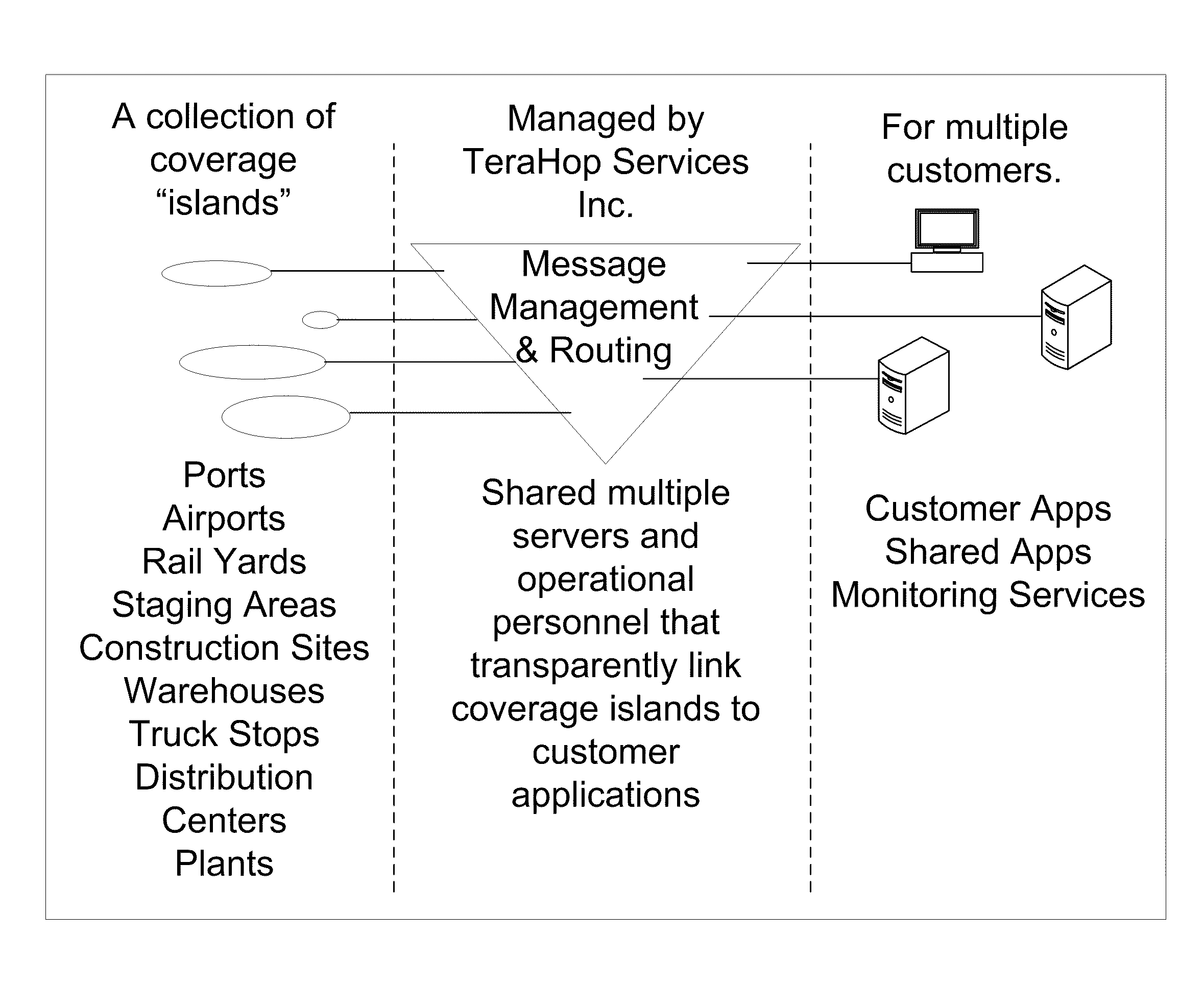
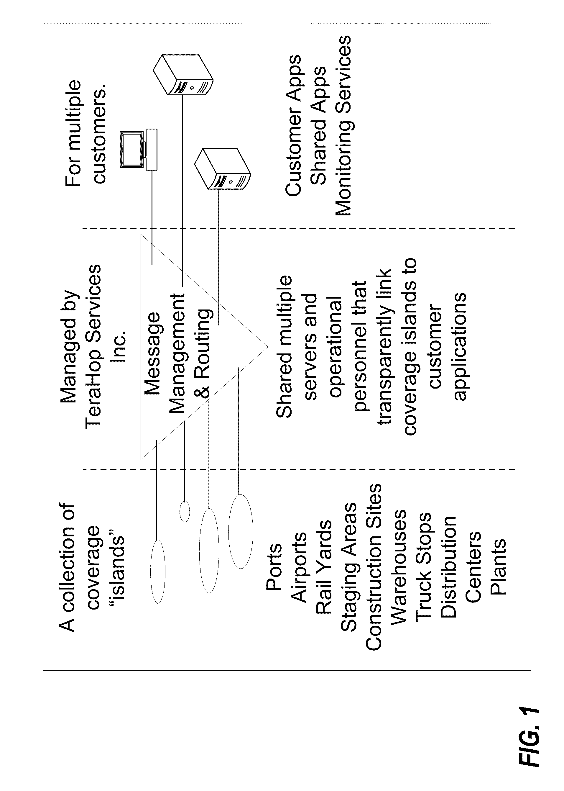
A system for monitoring and managing emergency services sector resources includes a wireless communications device configured to establish a wireless network, a plurality of wireless nodes wirelessly connected to the wireless network, a user application, a message management and routing system configured to facilitate communications between the wireless communication device and the user application, and a user device configured to display information from the user application. Each wireless node of the plurality of wireless nodes is associated with an emergency services sector resource, and is configured to communicate information regarding the emergency services sector resource to the user application via the wireless communications device. The user device is configured to display information regarding the emergency services sector resource from the user application.

Description

CROSS-REFERENCE TO RELATED APPLICATIONS[0001]The present application is a U.S. nonprovisional patent application of, and claims priority under 35 U.S.C. §119(e) to each of:[0002](a) U.S. Provisional Patent Application No. 61 / 140,887, filed Dec. 25, 2008, titled “UPDATING NODE PRESENCE BASED ON COMMUNICATION PATHWAY”;[0003](b) U.S. Provisional Patent Application No. 61 / 109,500, filed Oct. 29, 2008, titled SYSTEMS AND APPARATUS FOR MANAGING AND MONITORING EMERGENCY SERVICES SECTOR RESOURCES”;[0004](c) U.S. Provisional Patent Application No. 61 / 109,505, filed Oct. 30, 2008, titled “SYSTEMS AND APPARATUS FOR MANAGING AND MONITORING EMERGENCY SERVICES SECTOR RESOURCES”;[0005](d) U.S. Provisional Patent Application No. 61 / 109,502, filed Oct. 29, 2008, titled “SYSTEMS AND APPARATUS FOR MANAGING AND MONITORING EMERGENCY SERVICES SECTOR RESOURCES”;[0006](e) U.S. Provisional Patent Application No. 61 / 140,880, filed Dec. 25, 2008, titled “MERGING AND UNMERGING WIRELESS AD HOC NETWORKS”;[0007](...

Claims


Application Information

Patent Timeline
IPC IPC(8): H04B7/00G06Q10/00G06Q50/00
CPCG06Q10/06G06Q50/265G06Q10/08
Inventor BERGER, THOMAS R.DENNY, JOSEPH E.
Owner GOOGLE LLC
Why Eureka
Try Eureka