Eureka AIR delivers breakthrough ideas for toughest innovation challenges, trusted by R&D personnel around the world.

Skull Vibrational Unit

Active Publication Date: 2010-06-10
MED EL ELEKTROMEDIZINISCHE GERAETE GMBH
View PDF25 Cites 104 Cited by
  • Summary
  • Abstract
  • Description
  • Claims
  • Application Information

AI Technical Summary

Benefits of technology

[0015]There may also be a silicone elastomer receiver housing that contains the receiving coil. A titanium transducer housing may contain the bone conduction transducer. The bone conduction transducer may be suspended beneath the mounting points in a recess in the skull bone. An unbiased pivot may connect the receiving coil to the bone conduction transducer to allow positioning of the receiving coil and the bone conduction transducer in non-parallel planes without residual bias force.

Problems solved by technology

Interaction between the microphone and the speaker can sometimes cause an annoying and painful a high-pitched feedback whistle.
The amplified sound produced by conventional hearing aids also normally includes a significant amount of distortion.
Middle ear implants using electromagnetic transducers can present some problems.
Disarticulation deprives the patient of any residual hearing he or she may have had prior to surgery, placing the patient in a worsened position if the implanted device is later found to be ineffective in improving the patient's hearing.

Method used


Image

  • Skull Vibrational Unit
  • Skull Vibrational Unit
  • Skull Vibrational Unit

Examples


Embodiment Construction

[0029]FIG. 3 shows elements of an implantable hearing prosthesis as described, for example, in U.S. Patent Publication 20070191673 (“Ball '673”), which is based on driving a relatively large mass to vibrate the skull bone of a hearing impaired patient. Bone conduction of these vibrations is transduced into fluidic vibration within the cochlea that is sensed by the patient as sound. More specifically, FIG. 3A shows a top plan view and FIG. 3B shows a side cross-section view of an implantable hearing prosthesis 300 using an inertial mass-based bone conduction transducer. A silicone elastomer receiver housing 301 contains a receiving coil 302 that transcutaneously receives communications signals from the external audio processor, and a holding magnet 303 that cooperates with a corresponding external magnet to hold the external audio processor in correct position over the receiving coil 302. An implant signal processor 304 receives the communications signals from the receiving coil 302 ...


PUM


Abstract

An implantable hearing prosthesis for a recipient patient is described. An implantable receiving coil transcutaneously receives an externally generated communication data signal. An implantable signal processor is in communication with the receiving coil and converts the communication data signal into an electrical stimulation signal. An implantable transducer housing is fixedly attachable to skull bone of the patient. An implantable drive transducer is in communication with the signal processor and removably engageable with the transducer housing for applying to the transducer housing a mechanical vibration signal based on the electrical stimulation signal for audio perception by the patient.

Description

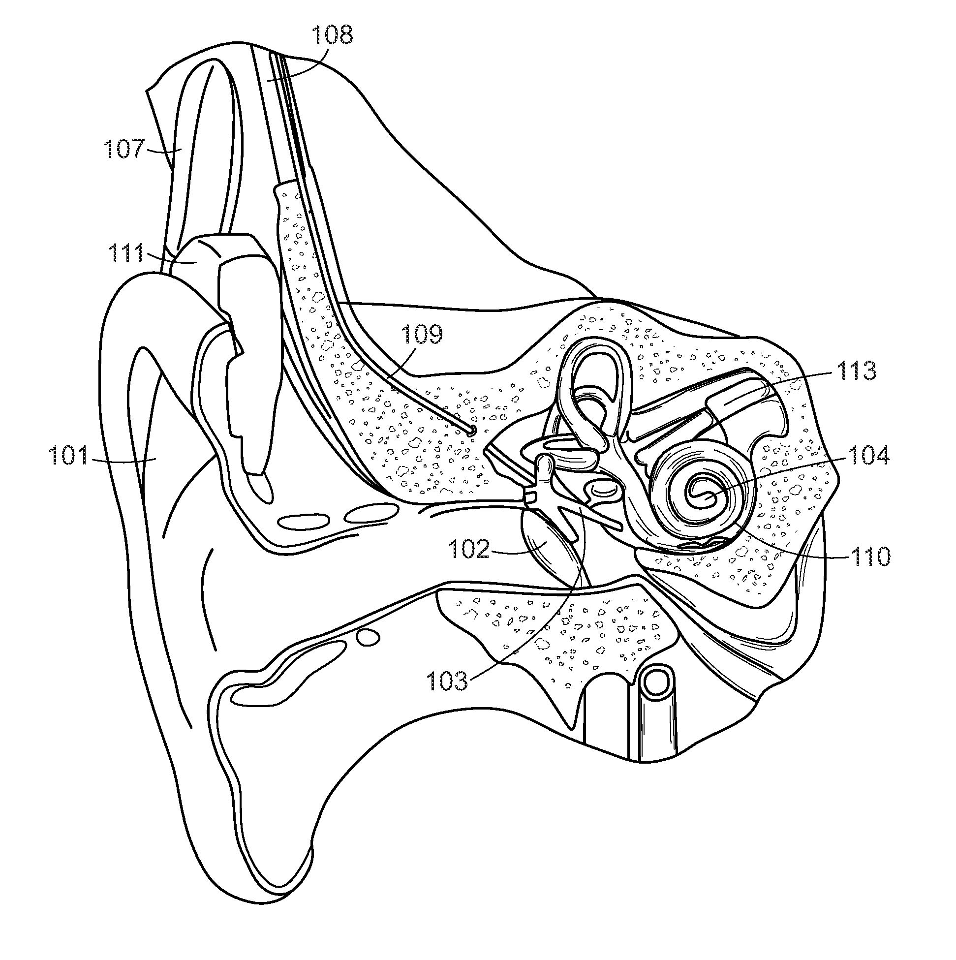
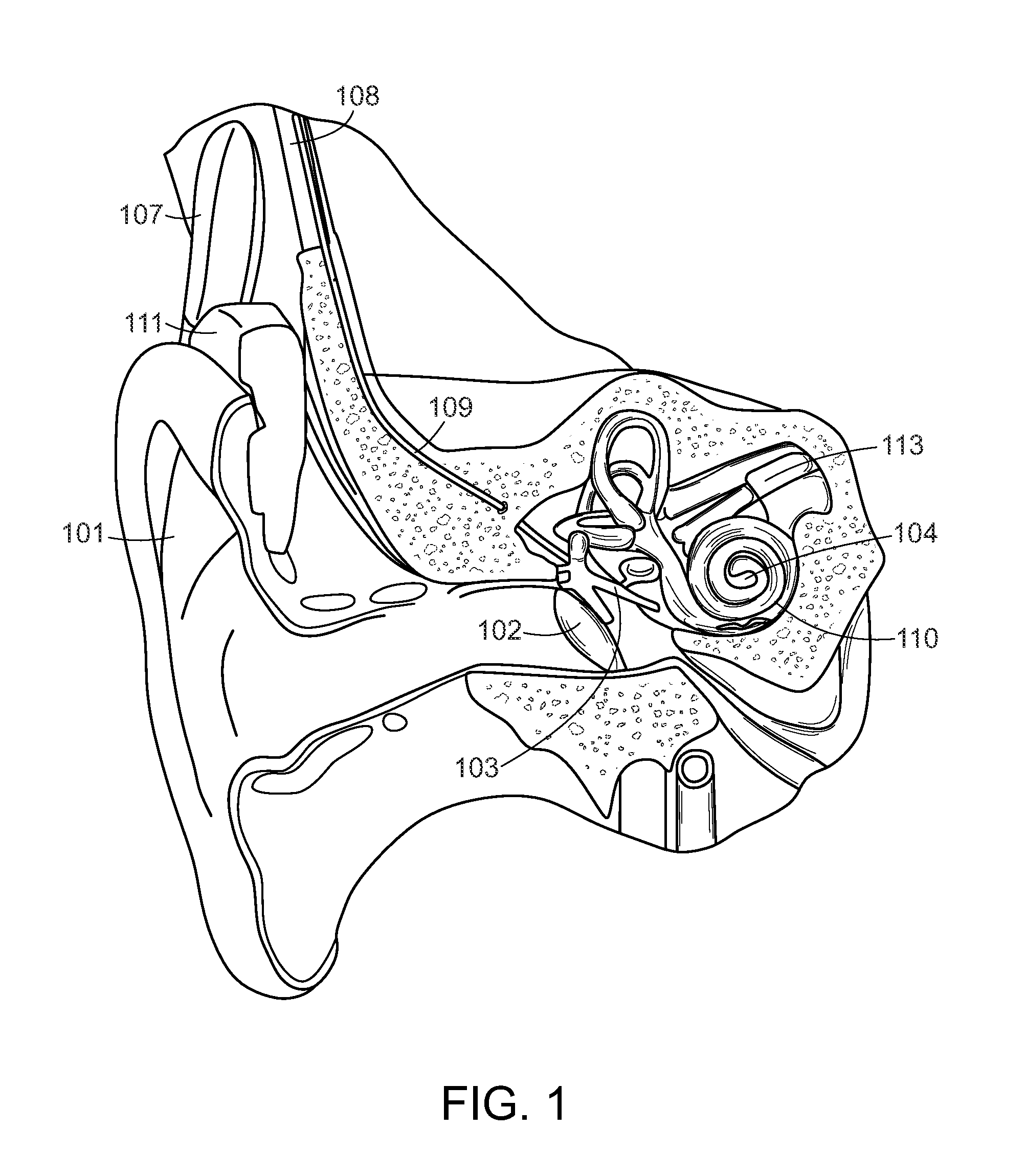
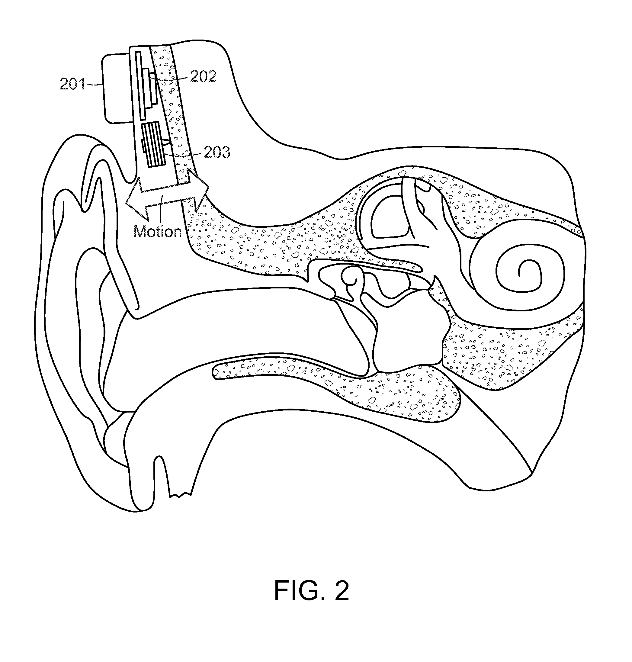
[0001]This application claims priority from U.S. Provisional Patent Application 61 / 263,150, filed Nov. 20, 2009, and from U.S. Provisional Patent Application 61 / 227,603, filed Jul. 22, 2009, and from U.S. Provisional Patent Application 61 / 121,399, filed Dec. 10, 2008, which are incorporated herein by reference.FIELD OF THE INVENTION[0002]The present invention relates to medical implants, and more specifically to a novel bone conduction transducer for an implantable hearing prosthesis.BACKGROUND ART[0003]A normal ear transmits sounds as shown in FIG. 1 through the outer ear 101 to the tympanic membrane (eardrum) 102, which moves the ossicles of the middle ear 103 (malleus, incus, and stapes) that vibrate the oval window and round window openings of the cochlea 104. The cochlea 104 is a long narrow organ wound spirally about its axis for approximately two and a half turns. It includes an upper channel known as the scala vestibuli and a lower channel known as the scala tympani, which a...

Claims


Application Information

Patent Timeline
IPC IPC(8): H04R25/00
CPCH04R25/606H04R2460/13H04R2225/67
Inventor BALL, GEOFFREYLAMPACHER, PETERAMRHEIN, WOLFGANGWEIDENHOLZER, GUNTHER
Owner MED EL ELEKTROMEDIZINISCHE GERAETE GMBH
Why Eureka
Eureka Blog
Learn More