Expandable spinal sheath and method of use

a spinal cord and expandable technology, applied in the field of medical devices, can solve the problems of weakening the malleable reinforcement elements, and achieve the effects of reducing the wall thickness, tensile strength and torqueability of the braid, and little or no spring properties

Active Publication Date: 2010-06-10
ONSET MEDICAL CORP
View PDF91 Cites 58 Cited by
  • Summary
  • Abstract
  • Description
  • Claims
  • Application Information

AI Technical Summary

Benefits of technology

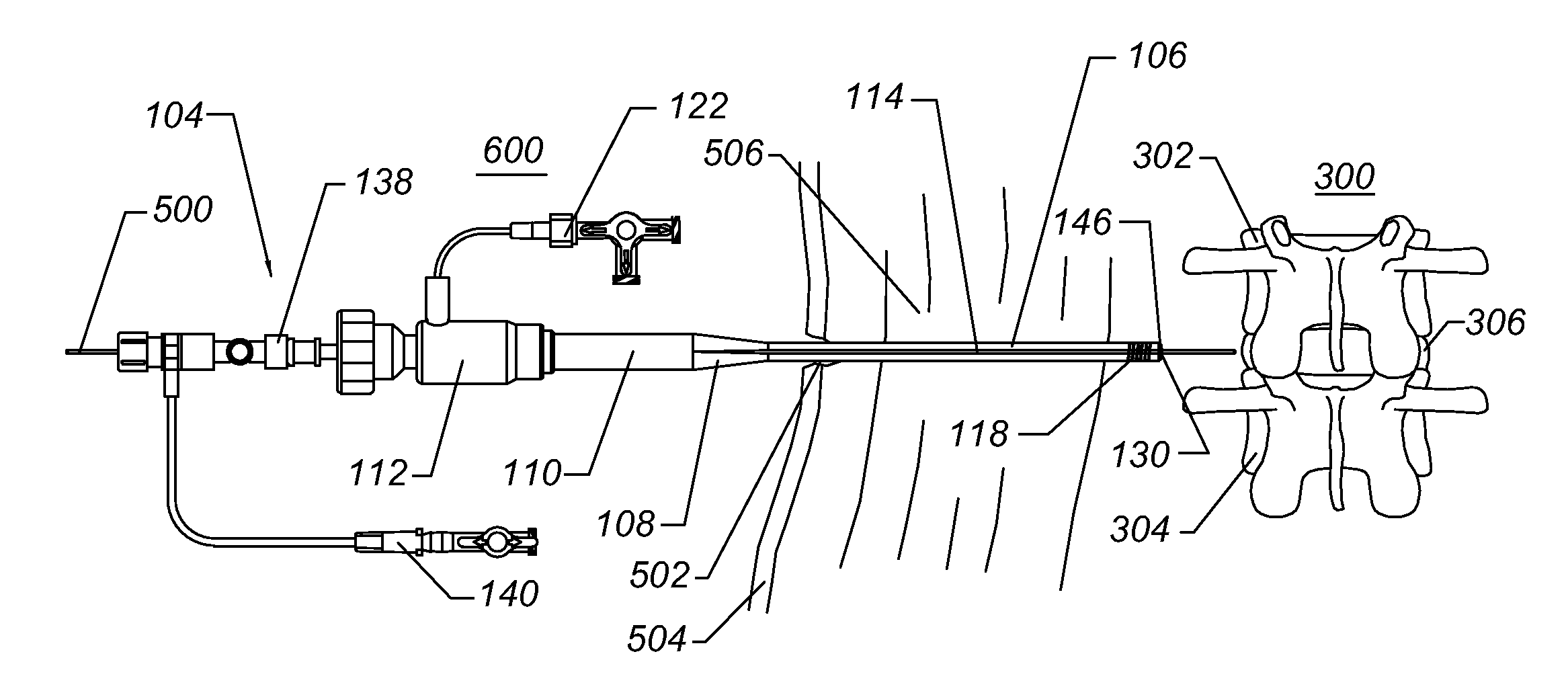
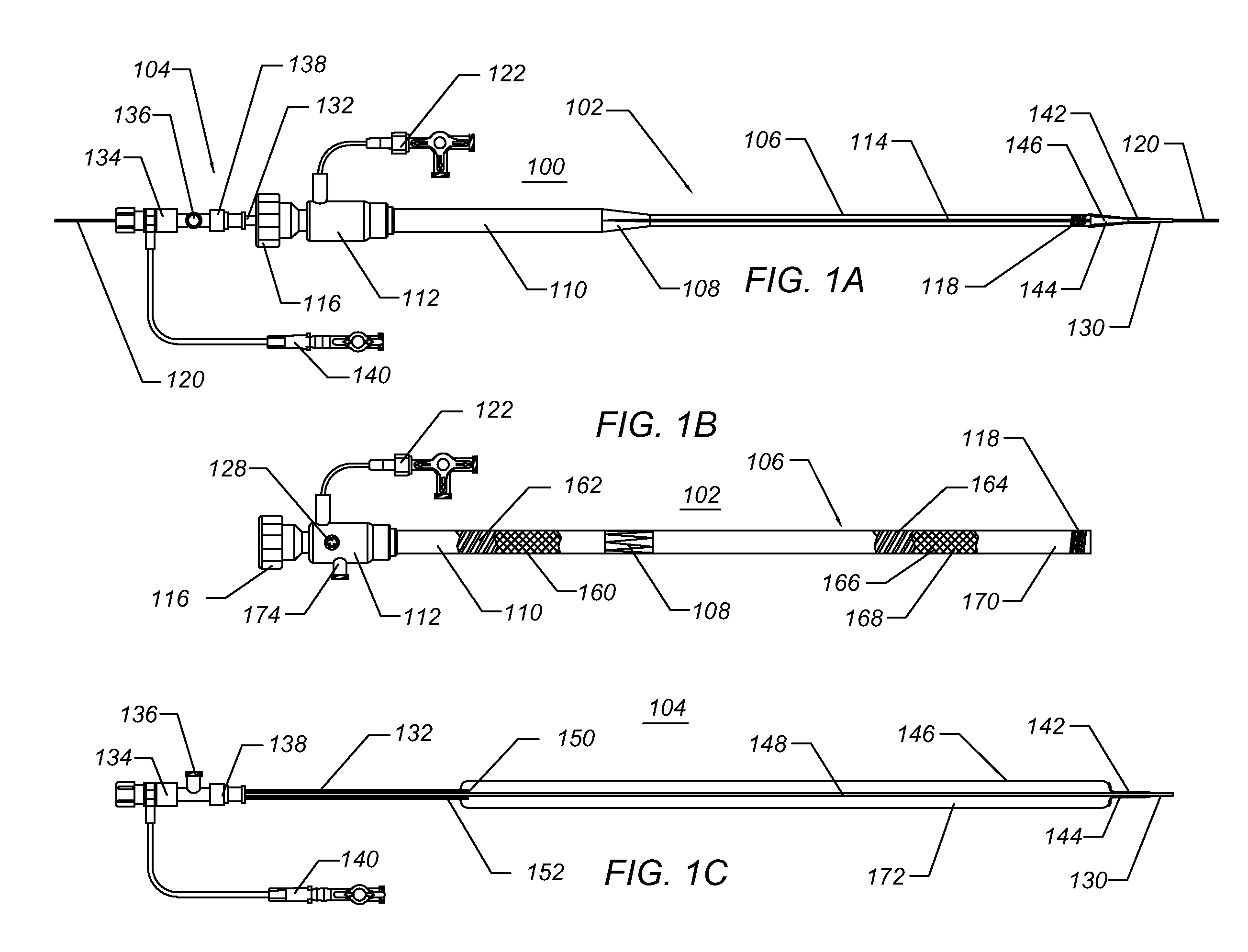
[0034]In certain embodiments of the sheath wall construction, an inner layer of polymer and an outer layer of polymer sandwich a reinforcing layer. The reinforcing layer can be a coil of metal such as, but not limited to, titanium, stainless steel, cobalt nickel alloy, nitinol, tantalum, and the like. In the distal, expandable region, the coil is preferably malleable, with little or no spring properties, and does not exhibit any elastomeric tendencies. The coil can be fabricated from flat wire with a thickness of about 0.001 to 0.010 inches and preferably about 0.002 to 0.005 inches. The width of the flat wire can range from about 0.005 to 0.050 inches and preferably from about 0.008 to 0.025 inches. The spacing between the coils can, for example range from substantially 0 to approximately 5 times the width of the coil wire. The coil spacing may be non-zero to permit bonding of the outer layer and the inner layer of polymer surround on the sheath, thus a coil spacing of about 0.5 to 3 times the coil width is preferred. The coils can be fabricated from round stock, flat stock, or the like. The reinforcement can be sandwiched between the inner layer and the outer layer of polymeric material, wherein the inner and outer layers can be bonded or welded to each other through the space between the coils. The inner and outer polymeric layers can be fabricated from the same or different materials. Suitable materials for the inner and outer layers include, but are not limited to, polyurethane, silicone, Hytrel, Pebax, PEEK, polyethylene (PE), high density polyethylene (HDPE), low density polyethylene (LDPE), polyester, polyethylene blends, and the like. In yet another embodiment, a plastically deformable, malleable, or annealed, braid structure can also be used for reinforcement to beneficially eliminate the need for the malleable coil and permit a reduction in wall thickness while retaining the tensile strength and torqueability of the braid.
[0035]In some embodiments, the sheath retains substantially constant flexibility moving from

Problems solved by technology

However, in one embodiment, the malleable reinforcing elements are not strong enough to resist remodeling or dilation forces exerted by a sheath dilator disposed

Method used


Image

  • Expandable spinal sheath and method of use
  • Expandable spinal sheath and method of use
  • Expandable spinal sheath and method of use

Examples


Embodiment Construction

[0057]The inventions may be embodied in other specific forms without departing from its spirit or essential characteristics. The described embodiments are to be considered in all respects only as illustrative and not restrictive. The scope of the inventions are therefore indicated by the appended claims rather than the foregoing description. All changes that come within the meaning and range of equivalency of the claims are to be embraced within their scope.

[0058]As used herein, a catheter or sheath can be described as an axially elongate structure having a proximal end, a distal end, and a lumen extending partially, or completely, therethrough. As used herein, the terms proximal and distal refer to directions or positions along a longitudinal axis of a catheter or medical instrument. Proximal refers to the end of the catheter or medical instrument closest to the operator, while distal refers to the end of the catheter or medical instrument closest to the patient. For example, a fir...


PUM


Abstract

Disclosed is an expandable percutaneous sheath, for introduction into the body while in a first, low cross-sectional area configuration, and subsequent expansion to a second, enlarged cross-sectional configuration. The sheath is maintained in the first, low cross-sectional configuration by a removable tubular restraint or by structural elements built into the wall of the expandable portion of the sheath. In one application, the sheath is utilized to introduce a formed in place orthopedic fixation rod such as for use in spinal fixation procedures, preparation of a spinal segment, or placement of a vertebral body spacer. The sheath can further comprise structural elements to permit re-collapse of the sheath under fluid pressure following completion of the procedure and prior to removal from the patient.

Description

PRIORITY CLAIM[0001]This application claims priority to 61 / 112,952, filed on Nov. 10, 2008, titled Expandable Spinal Sheath and Method of Use, the entirety of which are hereby incorporated herein by reference.BACKGROUND OF THE INVENTION[0002]1. Field of the Invention[0003]The present invention relates to medical devices and, more particularly, to methods and devices for forming a percutaneous channel. In one embodiment, the present invention relates to a minimally invasive procedure to insert an orthopedic fixation or stabilization implant into the body, such as a formed in situ spinal stabilization rod or performance of a lateral spinal stabilization or reconstruction procedure.[0004]2. Description of the Related Art[0005]The vertebrae and associated connective elements are subject to a variety of diseases and conditions, which cause pain and disability. Among these diseases and conditions are spondylosis, spondylolisthesis, vertebral instability, spinal stenosis and degenerated, h...

Claims


Application Information

Patent Timeline
IPC IPC(8): A61M29/00A61B1/32
CPCA61B17/1671A61B17/7083A61F2/4455A61F2/4611A61F2002/30787A61F2002/30904Y10S606/90A61F2310/00011A61F2310/00023A61M25/1011A61M29/02A61M2025/1065A61F2002/4435
Inventor BISHOP, JOSEPHLENKER, JAYNANCE, EDWARD J.NGUYEN, HUAN T.
Owner ONSET MEDICAL CORP
Why Eureka
Try Eureka