Hybrid power for cracking power plant co2

a power plant and hybrid technology, applied in the direction of machines/engines, mechanical equipment, greenhouse gas reduction, etc., can solve the problem of cracking of co2/sub>

Inactive Publication Date: 2010-06-17
MCCUTCHEN CO
View PDF4 Cites 23 Cited by
  • Summary
  • Abstract
  • Description
  • Claims
  • Application Information

AI Technical Summary

Problems solved by technology

CO2 is cracked whenever intermittent energy sources are availab

Method used


Image

  • Hybrid power for cracking power plant co2
  • Hybrid power for cracking power plant co2

Examples


Embodiment Construction

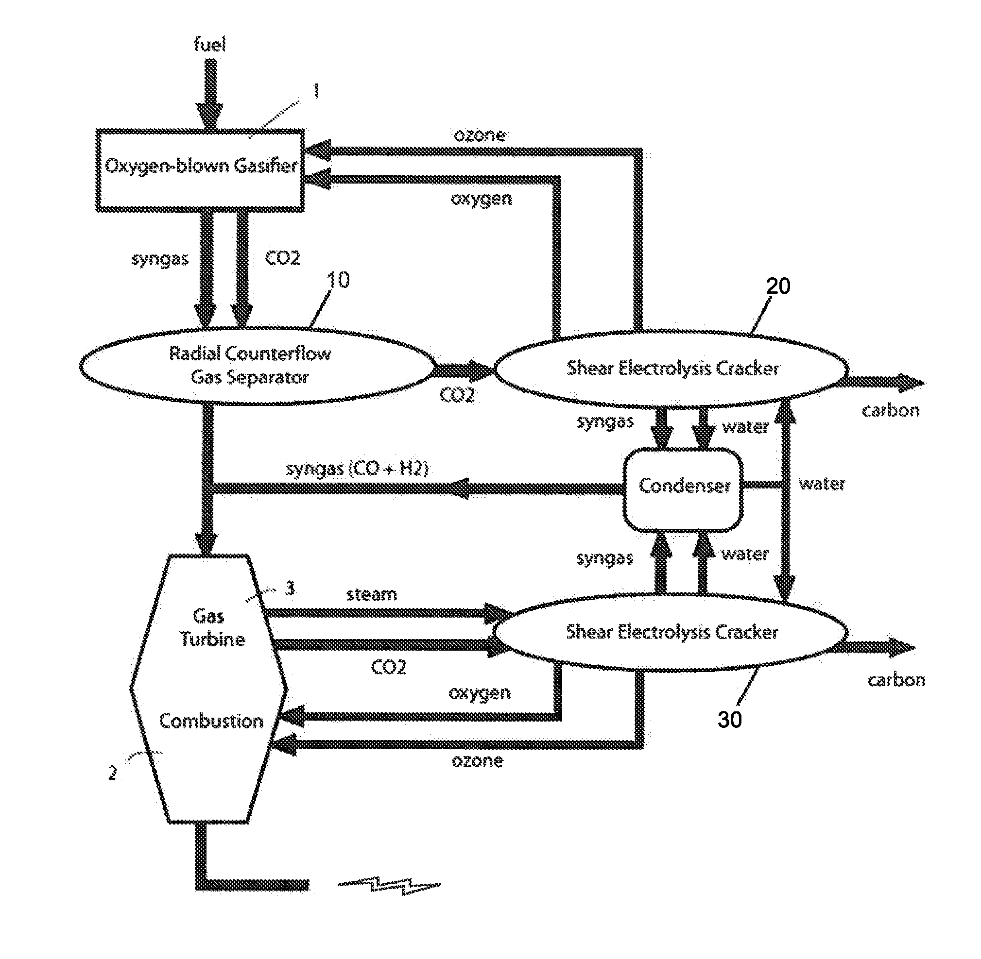
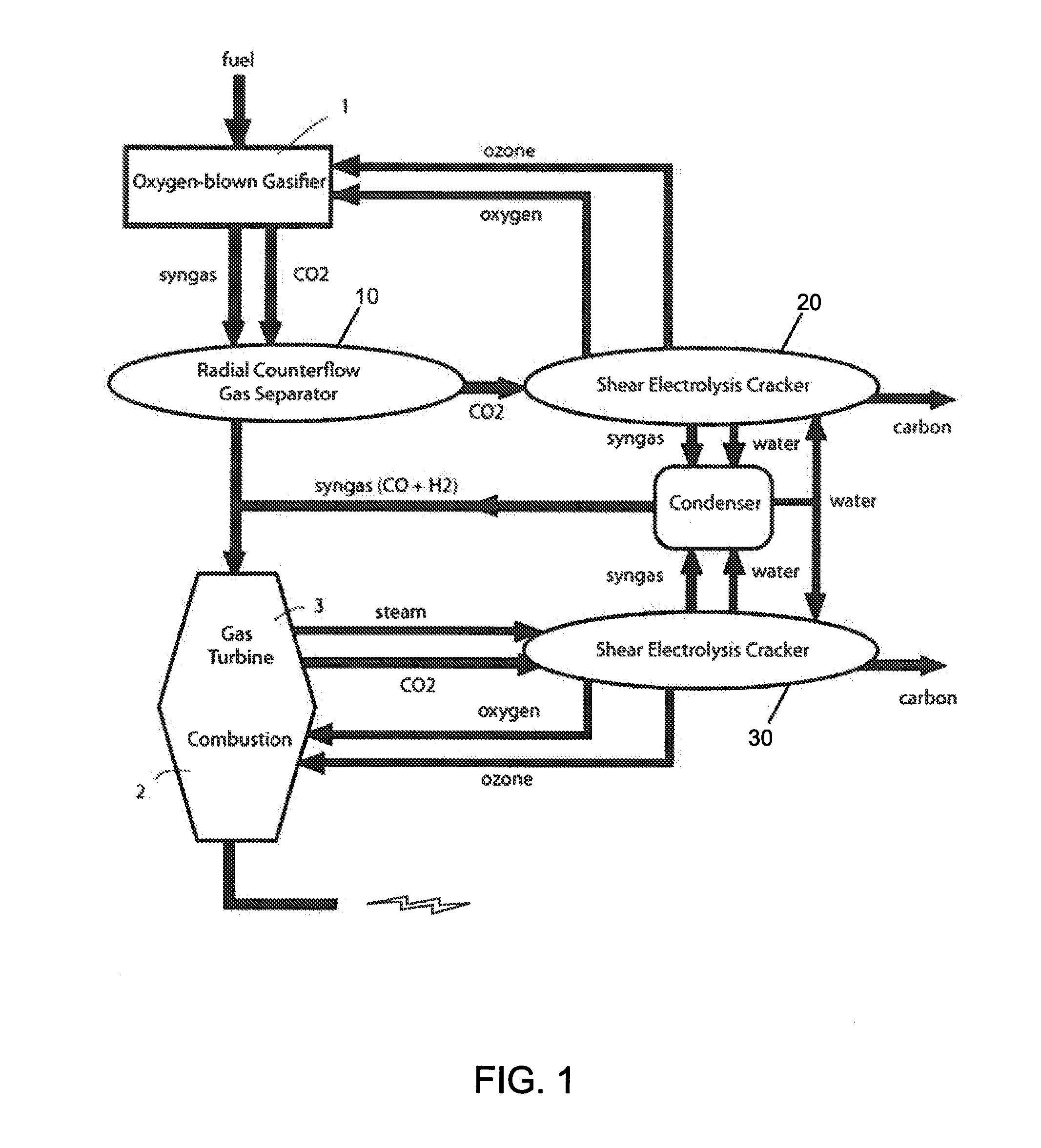
[0017]FIG. 1 shows a flow diagram of the hybrid power system of the present invention applied to a gasification power plant. Gasification power plants include those facilities which treat coal, biomass, landfill, or other carbonaceous fuels in a gasifier 1, producing syngas (a mixture of carbon monoxide and hydrogen) which can be processed into liquid fuel by the Fischer-Tropsch synthesis. A fraction of the output of the gasifier 1 is CO2. A gas separator 10—preferably of the radial counterflow type disclosed in U.S. patent application Ser. No. 11 / 827,634 entitled “Radial Counterflow Carbon Capture and Flue Gas Scrubbing,” by Wilmot H. McCutchen, filed Jul. 11, 2007, US Pat. App. No. 2009 / 0013867 (Jan. 15, 2009), incorporated by reference herein—separates CO2 from the gasifier output. The CO2 thus captured becomes feed to an electrolytic cracker 20—preferably of the radial counterflow type disclosed in U.S. patent application Ser. No. 12 / 167,771 entitled “Radial Counterflow Shear El...


PUM


Abstract

Power from wind, solar, and other intermittent energy sources cracks carbon dioxide, NOx, SOx, and other emissions from fossil fuel power plants, which provide baseload power to the grid. By this hybrid power system, intermittent sources can be integrated in power generation without compromising the reliability of the grid and without long power line connections. Carbon dioxide becomes, in effect, a storage medium for energy produced by intermittent sources. The CO2 can be pipelined to sites where wind, solar, tidal or and other intermittent energy sources are available, or power lines can be run from such intermittent sources to convenient sites for cracking.

Description

BACKGROUND OF THE INVENTION[0001]“Sequestration” (pumping enormous volumes of CO2 underground and hoping it won't leak out) is impractical for overwhelming technical and political reasons. The clear and convincing case against carbon dioxide sequestration, published by the GAO, can be found at http: / / www.gao.gov / new.items / d081080.pdf. A need exists for an alternative to sequestration, and the present invention addresses that need.[0002]A preferable approach is to crack captured carbon dioxide and thereby render it harmless, or even useful. Useful cracking byproducts may include syngas, solid carbon, and oxygen. In pending U.S. patent application Ser. No. 12 / 167,771 entitled “Radial Counterflow Shear Electrolysis” by Wilmot H. McCutchen and David J. McCutchen, filed Jul. 3, 2008, US Pat. App. No. 2009 / 0200176 (published Aug. 13, 2009), we disclosed a device for cracking carbon dioxide as well as other pollutants between axially-fed counter-rotating disk dynamo electrodes. The present...

Claims


Application Information

Patent Timeline
IPC IPC(8): F02C6/00
CPCF02C3/28F03D9/00F03D9/02F05B2220/61F05D2220/722Y02E20/16Y02E10/72Y02E20/14Y02E20/18Y02E70/10F05D2260/61F03D9/19Y02E60/36Y02E70/30
Inventor MCCUTCHEN, WILMOT H.MCCUTCHEN, DAVID J.
Owner MCCUTCHEN CO
Why Eureka
Try Eureka