Burner for a combustor of a turbogroup

a turbogroup and combustion chamber technology, applied in the ignition of turbine/propulsion engines, combustion types, lighting and heating apparatus, etc., can solve the problem of the risk of a flame flashback from the combustion chamber into the burner interior, and achieve the effect of increasing the stability of the combustion process

a turbogroup and combustion chamber technology, applied in the ignition of turbine/propulsion engines, combustion types, lighting and heating apparatus, etc., can solve the problem of the risk of a flame flashback from the combustion chamber into the burner interior, and achieve the effect of increasing the stability of the combustion process

US20100146983A1Inactive Publication Date: 2010-06-17ANSALDO ENERGIA IP UK LTD

Image

  • Burner for a combustor of a turbogroup
  • Burner for a combustor of a turbogroup
  • Burner for a combustor of a turbogroup

Examples


Embodiment Construction

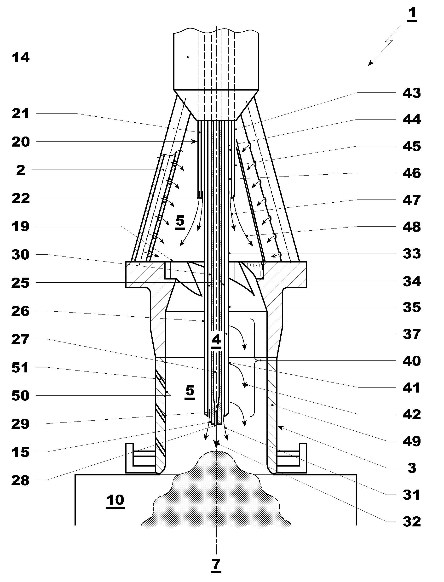
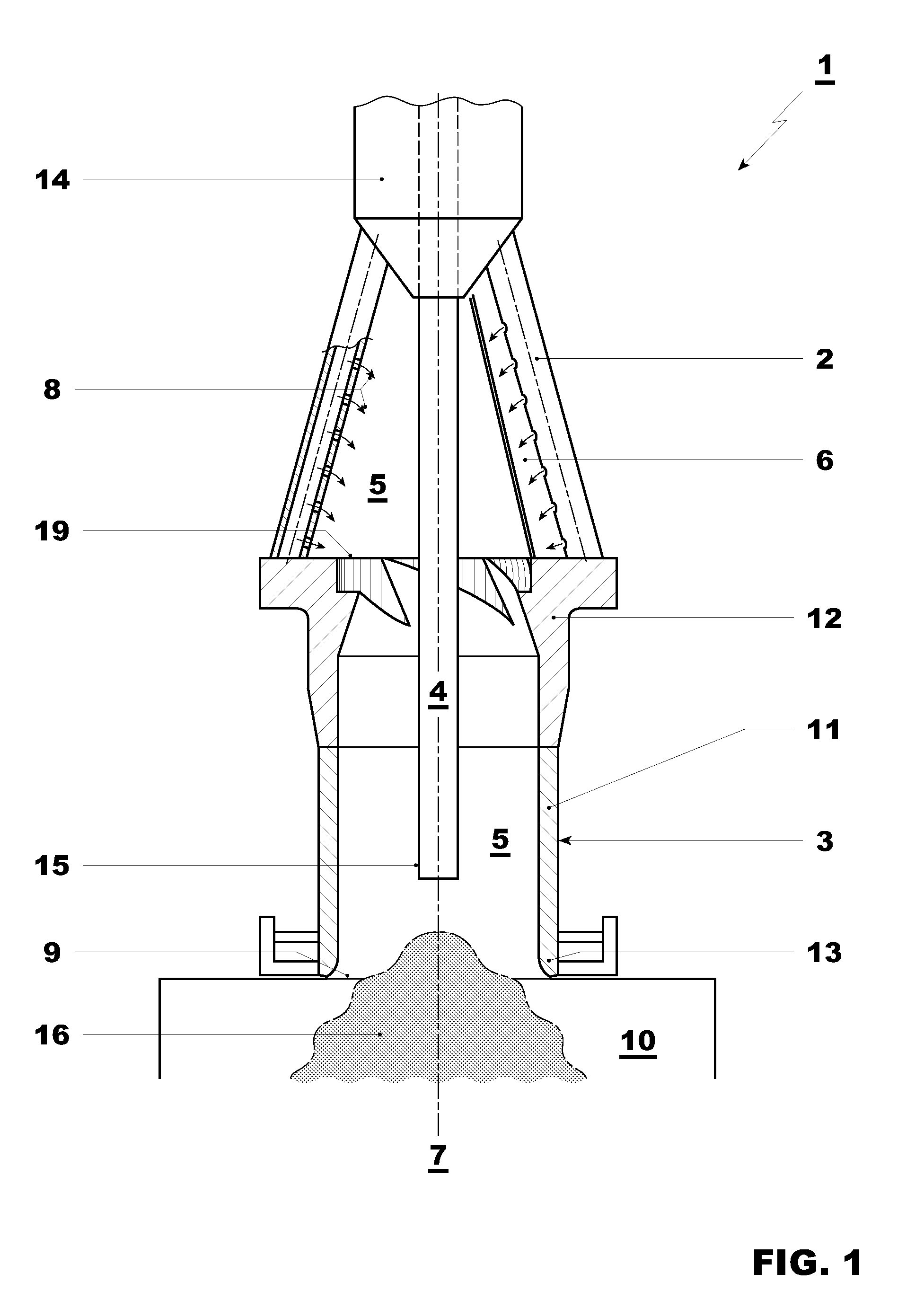
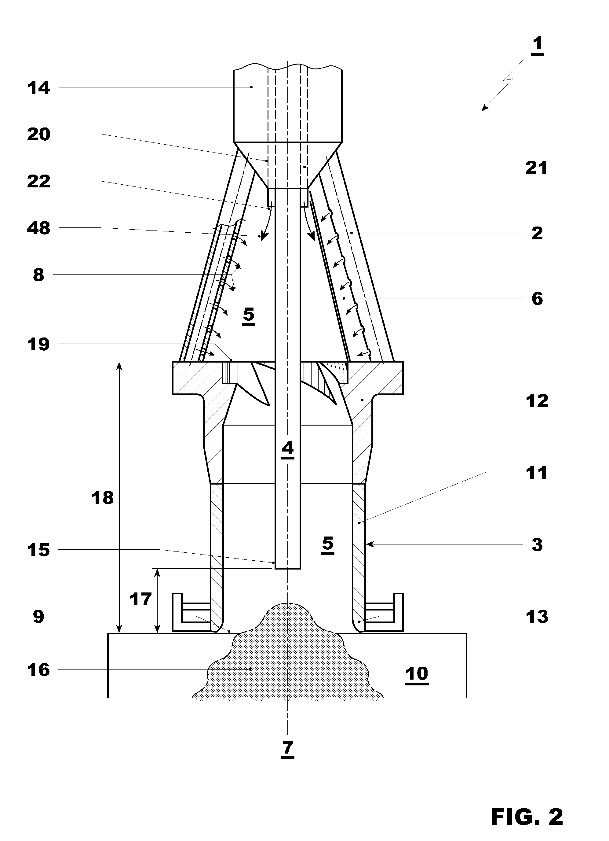
[0017]According to FIGS. 1 to 5, a burner 1 includes a swirl generator 2, a mixer 3, and a lance 4. The burner 1 in the installed state forms a component part of a combustion chamber, which is not otherwise shown here, of a turbogroup which is especially arranged in a power plant.

[0018]The swirl generator 2 encloses an inlet-side section of a burner interior 5 and has at least one air inlet 6 which extends tangentially with regard to a longitudinal center axis 7 of the burner 1. In the case of the examples which are shown, the swirl generator 2 is conically designed. The respective air inlet 6 in this case forms a longitudinal slot along the generated surface of the cone. A plurality of such air inlets 6 are preferably arranged in a distributed manner in the circumferential direction. As a result of this, the air can penetrate tangentially into the burner interior 5, as a result of which a swirl is imparted to it. In the case of the examples which are shown, the swirl generator 2 al...


PUM


Abstract

A burner (1) for a combustion chamber of a turbogroup includes a swirl generator (2), a mixer (3), and a lance (4) for introducing pilot fuel into a combustion space (10). In order to stabilize combustion, the lance (4) is designed and / or arranged so that, at least in the pilot mode of the burner (1), it extends far enough into the burner interior (5) for a flame front (16) of a combustion reaction, which takes place in the combustion space (10), to extend at least partially into the burner interior (5).

Description

[0001]This application is a Continuation of, and claims priority under 35 U.S.C. §120 to, International application no. PCT / EP2008 / 059321, filed 16 Jul. 2008, and claims priority therethrough under 35 U.S.C. §119, 365 to German application no. 10 2007 037 289.4, filed 7 Aug. 2007, the entireties of which are incorporated by reference herein.BACKGROUND[0002]1. Field of Endeavor[0003]The present invention refers to a burner for a combustion chamber of a turbogroup, especially in a power plant.[0004]2. Brief Description of the Related Art[0005]Such burners have a swirl generator which encloses a burner interior on the inlet side and has at least one tangential air inlet with regard to a longitudinal center axis of the burner. In addition, such a burner includes a mixer which encloses the burner interior on the outlet side and has an outlet opening which is open to a combustion space of the combustion chamber. Furthermore, such a burner can be equipped with a lance for introducing pilot...

Claims


Application Information

Patent Timeline
17 Jun 2010
Publication
US20100146983A1
IPC
F23D14/58; F23D14/62; F23D14/02
CPC
F23C2900/07002; F23C2900/07021; F23R3/343; F23R3/286; F23D2900/00015
Inventors
HELLAT, JAAN; EROGLU, ADNAN