
Heat exchanger for temperature control of vehicle batteries

a battery and temperature control technology, applied in the direction of lighting and heating apparatus, cell components, cell component details, etc., can solve the problems of battery not being able to provide its maximum output, battery cooling cannot be integrated into the engine cooling system of a hybrid vehicle, and unable to provide unprepared ambient or outside air cooling, etc., to achieve the effect of generating minimum noise and high cooling outpu

Active Publication Date: 2010-06-17
HANON SYST
View PDF38 Cites 34 Cited by
  • Summary
  • Abstract
  • Description
  • Claims
  • Application Information

AI Technical Summary

Benefits of technology

The invention is a heat exchanger for controlling the temperature of battery units in electric vehicles. The heat exchanger is designed to be compact and space-saving, with minimal installation space required. It uses flat tubes that are passable by a heat carrier and has a holding frame for positioning and fixing the battery units. The heat exchanger is designed to provide optimal conditions for heat transfer and minimize noise. The heat exchanger can be used with different battery units and heat carriers without needing to adapt other components within the battery. The walls of the heat exchanger are established by heat conducting sheets, which ensure even temperature distribution on the surface of the heat exchanger. The chambers that accommodate the battery units are segmented by the heat conducting sheets for easy mounting of the battery units.

Problems solved by technology

A cooling device for the battery cannot be integrated into the engine cooling system of a hybrid vehicle due to too high temperatures of up to about 100° C. within the engine cooling system.
But on a hot summer day, the temperature of the outside air can reach, or even exceed, 40° C., so that cooling based on unprepared ambient or outside air is not possible.
But the disadvantage arises that the battery cannot provide its maximum output.
Use of cooling air taken from the inside of the passenger compartment enables a narrower temperature range compared with the use of ambient air, but taking air from the passenger compartment increases the noise in the vehicle, hence reducing the passengers' comfort.
Further, when an air-based cooling system is used, in addition to the aforementioned loud flow-borne noise and the cooling output being dependent on the ambient conditions, large space requirements for air ducting and the necessary fans are extremely disadvantageous.
The heat-generating elements are firmly integrated into the heat exchanger that due to the wide flow cross-sections on the heat carrier side with external dimensions has a disadvantageously very large installation space.
Therefore, a disadvantageously large installation space of the heat exchanger, and hence, of the storage device is required.
Wide temperature spreads between the individual battery or storage cells, on the other hand, have a negative effect on the cell life.

Method used


Image

  • Heat exchanger for temperature control of vehicle batteries
  • Heat exchanger for temperature control of vehicle batteries
  • Heat exchanger for temperature control of vehicle batteries

Examples


Embodiment Construction

[0058]The following detailed description and appended drawings describe and illustrate various exemplary embodiments of the invention. The description and drawings serve to enable one skilled in the art to make and use the invention, and are not intended to limit the scope of the invention in any manner. It is understood that materials other than those described can be used without departing from the scope and spirit of the invention. In respect of the methods disclosed, the steps presented are exemplary in nature, and thus, the order of the steps is not necessary or critical.

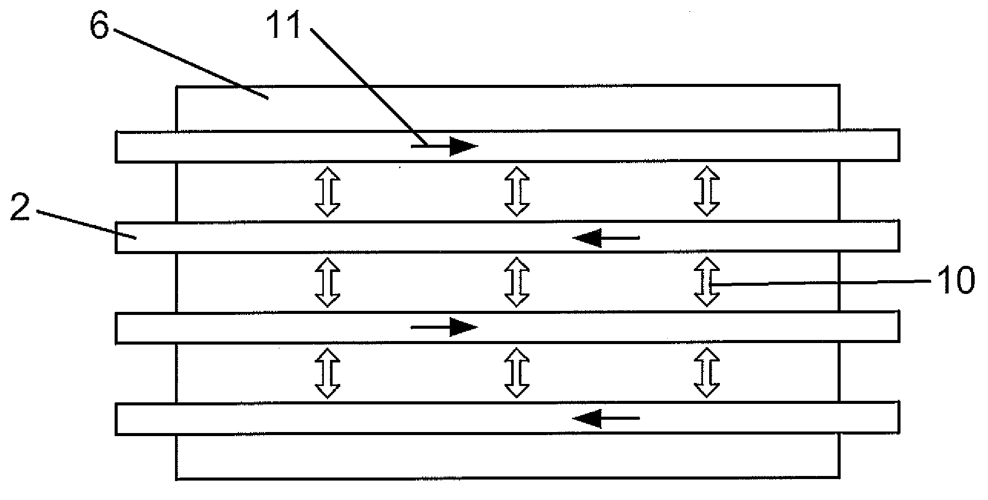
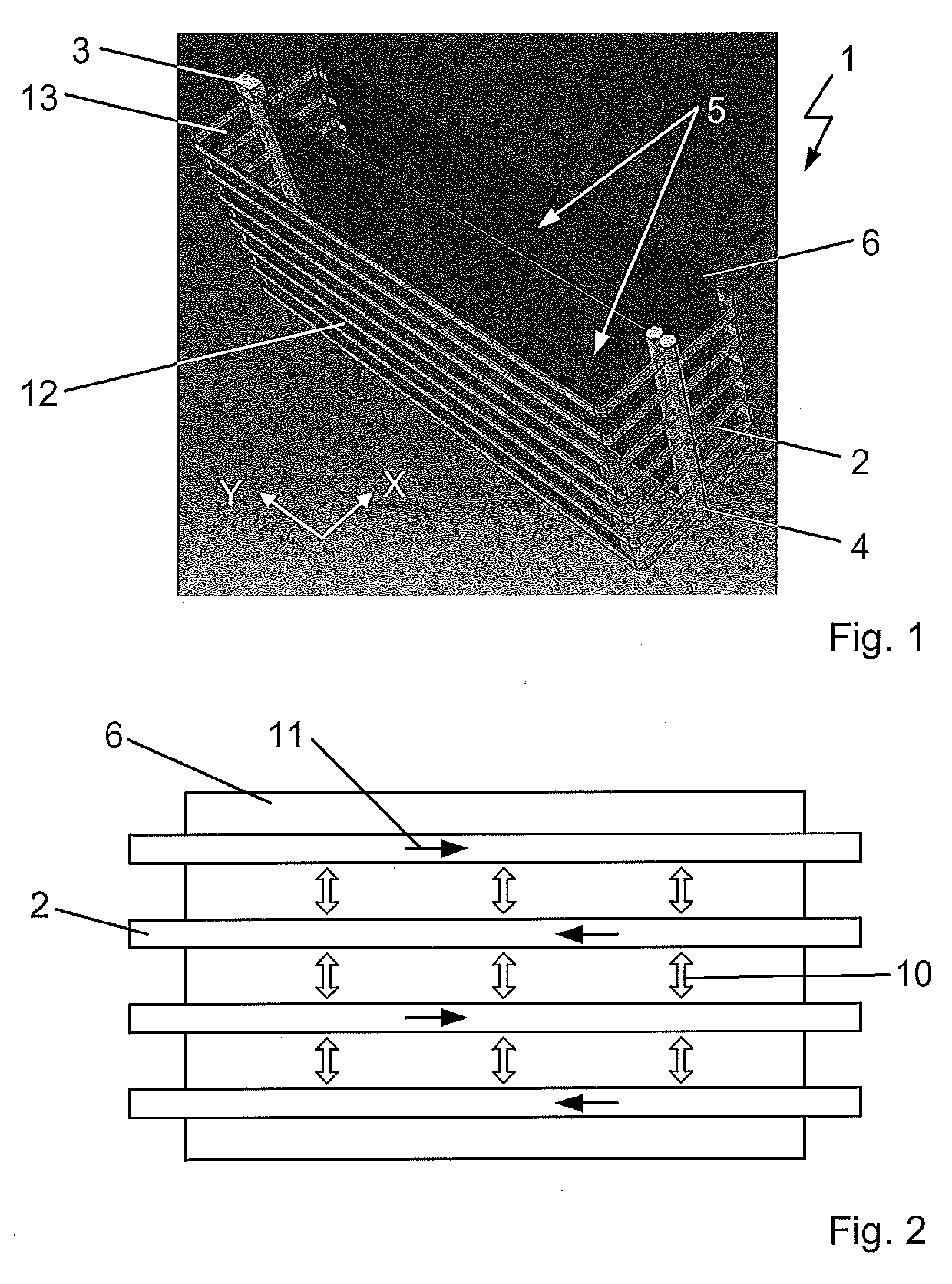
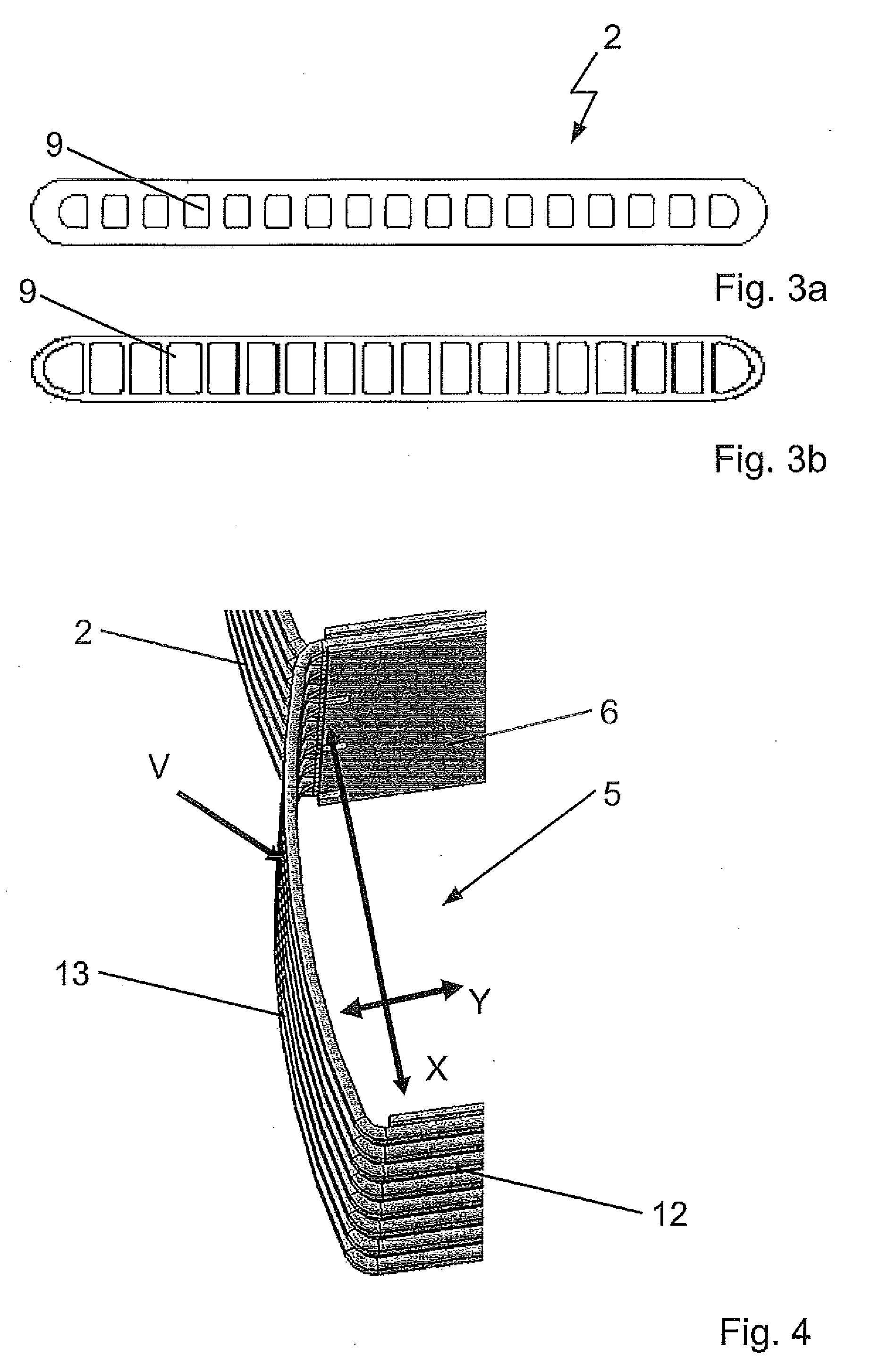
[0059]In FIG. 1, the heat exchanger (1) according to the invention with chambers (5) for accommodating battery units is shown, the battery units being cooled by means of the heat exchanger (1). The heat exchanger (1) passed by a heat carrier dissipates the heat that develops during operation of the battery units, that means, during charging and discharging, such ensuring that the battery does not exceed a defin...


PUM


Abstract

The invention relates to a heat exchanger for temperature controlling and fastening of battery units of the battery of a vehicle. The heat exchanger includes flat tubes that are passable by a heat carrier and a collecting tube and distributing tube for conducting the heat carrier. The flat tubes are established as multi-channel flat tubes. The collecting tube and the distributing tube are connected to each other over the flat tubes so that a holding frame is established that provides a structure forming spaces. The spaces are provided as chambers for accommodating the battery units.

Description

CROSS-REFERENCE TO RELATED APPLICATION[0001]This application claims priority to German Patent Application No. DE 10 2008 054 680.1 filed Dec. 15, 2008 and German Patent Application No. DE 10 2009 029 629.8 filed Sep. 21, 2009, the entire disclosures of which are hereby incorporated herein by reference.FIELD OF THE INVENTION[0002]The invention relates to a heat exchanger for temperature control and fastening of battery units in a vehicle, especially a hybrid or electric vehicle.BACKGROUND OF THE INVENTION[0003]The high-capacity batteries used in electric or hybrid vehicles serve to store electric energy. In an electric vehicle, the battery is supplied with energy by connecting it to a power source. In hybrid vehicles, energy can additionally be recovered during braking of the vehicle.[0004]In operation, that is on charging or decharging, or when the stored energy is taken from the battery, heat is released. Batteries possess an optimal operating temperature so that the developed heat...

Claims


Application Information

Patent Timeline
Patent Type & Authority Applications(United States)
IPC IPC(8): F24H9/02F28D7/00F28F1/10
CPCH01M2/1077H01M10/5004H01M10/5008H01M10/5016H01M10/5032H01M10/5059F28D2021/0071H01M10/5079F28F2280/00F28D1/0476F28F1/022F28D2021/0043H01M10/5075H01M10/625H01M10/647H01M10/6569H01M10/6557H01M10/6567H01M10/617H01M10/613Y02E60/10
Inventor PIERRE, ERIC D.GRAAF, MARCWIESCHOLLEK, FLORIANGIRMSCHEID, FELIX
Owner HANON SYST
Learn More