Range finding in imaging reader for electro-optically reading indicia

an imaging reader and range finding technology, applied in instruments, sensing record carriers, sensing by electromagnetic radiation, etc., can solve the problems of adding component and manufacturing costs, and adding system complexity

Inactive Publication Date: 2010-06-17
SYMBOL TECH INC
View PDF5 Cites 19 Cited by
  • Summary
  • Abstract
  • Description
  • Claims
  • Application Information

AI Technical Summary

Benefits of technology

[0011]The imager may be associated with an illumination assembly under control of the controller to illuminate the symbol and enable image capture to be acquired in a very short period of time, for example, on the order of 500 microseconds, so that the image is not blurred even if there is relative motion between the imager and the symbol. The illumination light is preferably brighter than ambient light. The illumination light can also be continuous. The imager is exposed by the controller and captures light over an exposure time period, also under the control of the controller. A short exposure time period also prevents image blurring.
[0014]Advantageously, an imaging lens assembly is also supported by the housing and is operative for imaging the pair of spots onto the imager at a separation distance. The controller measures the separation distance on the imager to determine the target distance. The imager captures the return light during the exposure time period. The controller continuously energizes the laser during the exposure time period.

Problems solved by technology

However, this approach adds component and manufacturing expense.
Still further, sometimes it is undesirable to require parallax to be deliberately designed into the reader.
Although generally satisfactory for its intended purpose, this approach adds component and manufacturing expense, as well as system complexity.
However, this approach reduces the brightness or intensity level of the aiming pattern, as well as of the return light, and requires complex high-speed electronic circuitry.

Method used


Image

  • Range finding in imaging reader for electro-optically reading indicia
  • Range finding in imaging reader for electro-optically reading indicia
  • Range finding in imaging reader for electro-optically reading indicia

Examples


Embodiment Construction

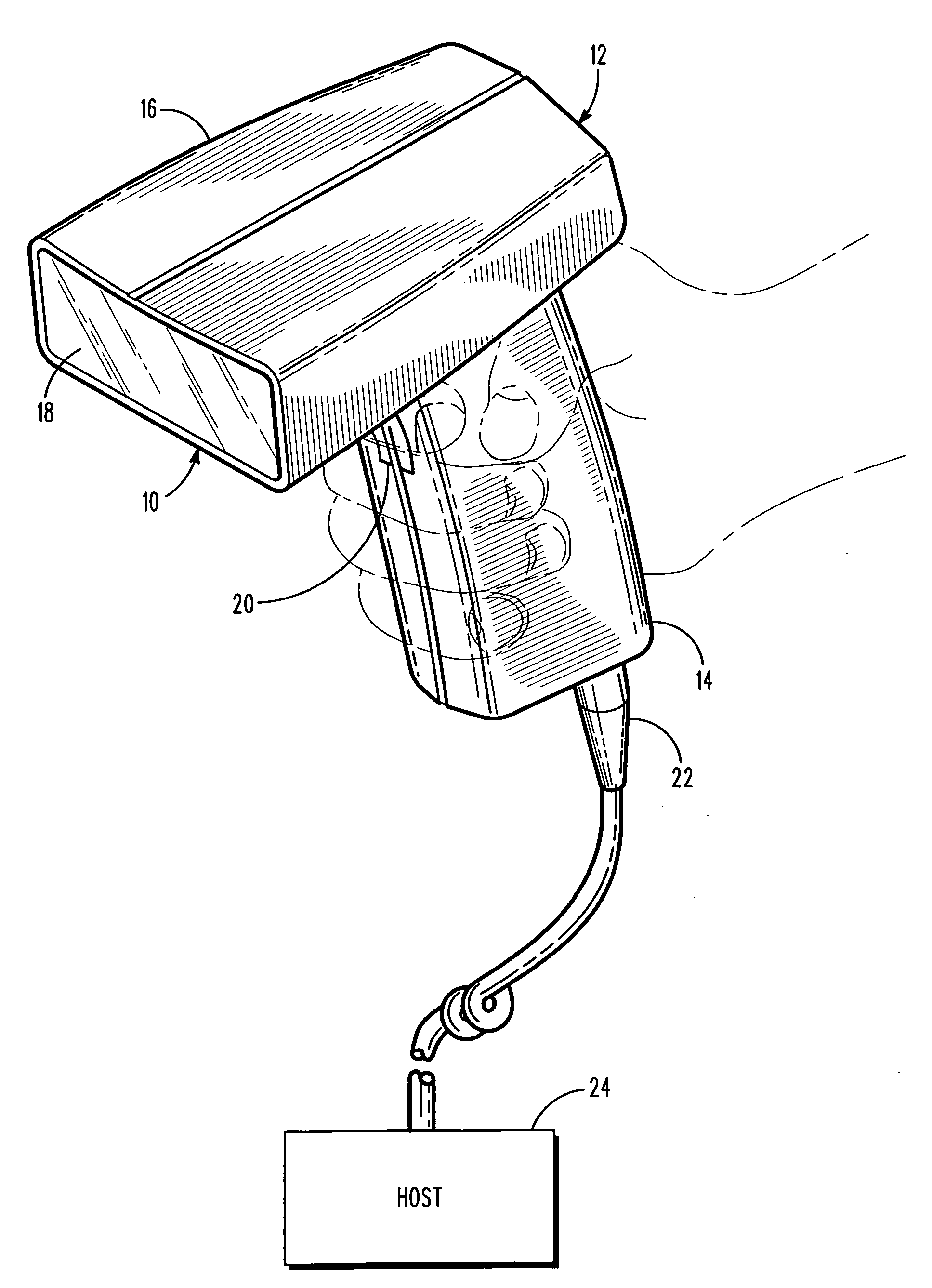
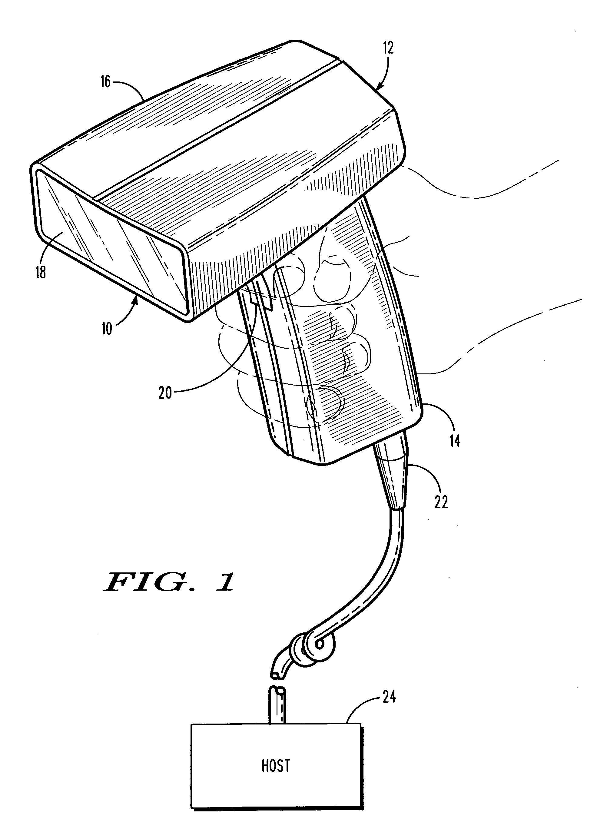
[0022]Reference numeral 10 in FIG. 1 generally identifies a handheld imaging reader for electro-optically reading symbols or like indicia on products or like targets. The reader 10 includes a housing 12 in which an aiming light assembly, as described in detail below in accordance with this invention, is incorporated. The housing 12 includes a generally elongated handle or lower handgrip portion 14 and a barrel or upper body portion 16 having a front end at which a light-transmissive window 18 is located. The cross-sectional dimensions and overall size of the handle are such that the reader can conveniently be held in an operator's hand.

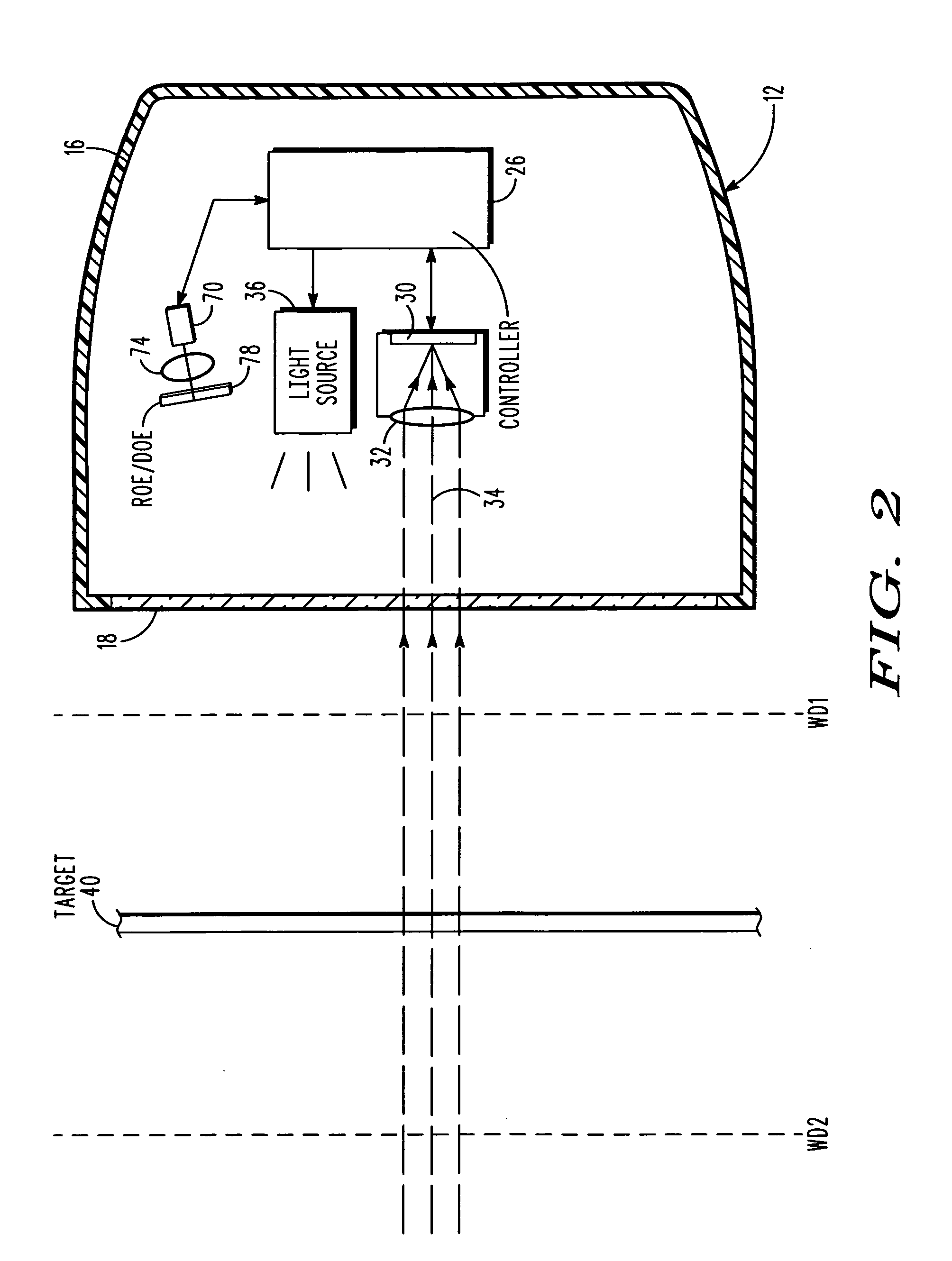
[0023]The body and handle portions may be constructed of a lightweight, resilient, shock-resistant, self-supporting material such as a synthetic plastic material. The plastic housing may be injection molded, but can be vacuum-formed or blow-molded to form a thin hollow shell which bounds an interior space whose volume is sufficient to contain the vari...


PUM


Abstract

An aiming light assembly of an imaging reader projects on a target, during an aiming mode of operation, an aiming light pattern that varies as a function of distance between a movable housing and the target. A solid-state imager captures light from the aiming light pattern during the aiming mode, and generates an electrical distance signal indicative of a target distance between the housing and the target. The imager also captures return light over a field of view from the target during a reading mode of operation after the aiming mode, and generates an electrical target signal indicative of the target. A controller processes the electrical distance signal during the aiming mode into data indicative of the target distance, and also processes the electrical target signal during the reading mode into data indicative of the target located at the target distance.

Description

BACKGROUND OF THE INVENTION[0001]Solid-state imaging readers have been used in supermarkets, warehouse clubs, department stores, and other kinds of retailers to capture light from various targets, for example, to electro-optically read one-dimensional bar code symbols, particularly of the Universal Product Code (UPC) type, on products to be purchased, each symbol having a row of bars and spaces spaced apart along one direction, and also for processing two-dimensional symbols, such as Code 49, as well as to capture light from other non-symbol targets. The structure of Code 49, which introduced the concept of vertically stacking a plurality of rows of bar and space patterns in a single symbol, is described in U.S. Pat. No. 4,794,239. Another two-dimensional symbol that increases the amount of data that can be represented or stored on a given amount of surface area of a target is known as PDF417 and is described in U.S. Pat. No. 5,304,786.[0002]A typical imaging reader includes a solid...

Claims


Application Information

Patent Timeline
Patent Type & Authority Applications(United States)
IPC IPC(8): G06K7/10
CPCG06K7/10712G06K2207/1011G06K7/10801
Inventor GUREVICH, VLADIMIR
Owner SYMBOL TECH INC
Why Eureka
Try Eureka