Valve arrangement

a valve arrangement and valve technology, applied in the direction of valve arrangement, plug valve, machine/engine, etc., can solve the problems of inability to utilize the valve arrangement, strong sealing, and inability to collect generated particles, etc., to achieve the effect of simple structure, no worsening of start-up torque and high reliability

Inactive Publication Date: 2010-06-17
VAT HLDG AG
View PDF11 Cites 42 Cited by
  • Summary
  • Abstract
  • Description
  • Claims
  • Application Information

AI Technical Summary

Benefits of technology

[0007]The present invention consequently addresses the problem of eliminating the disadvantages of prior art. The present invention in particular addresses the problem of providing a valve arrangement of the butterfly type, in which no abrading and frictional movements occur on the seal and the start-up torque does not worsen even after relatively long standing and operating times. The valve arrangement should, moreover, be simple of structure, attain high reliability and be economically producible.
[0011]The rotational axis is located on one side of the valve seat disk and extends transversely to the housing part or to the direction of flow. It can be located centrally with respect to the cross section of the housing part or preferably minimally offset or asymmetrical. The valve plates are supported rotatably and swivelably about this rotational axis on both sides on the housing part. Small shaft parts can be provided for this purpose on both sides whose axes correspond with the rotational axis and which are disposed on both sides on the two valve plates, such that these can be swiveled onto the associated openings in the valve seat disk for closing the valve with the formation of a sealing. Instead of short shaft parts, a continuous shaft piece can also be utilized. At least on one side of the housing part the shaft part or the shaft is carried to the outside through this part via a shaft seal in order to make it feasible to be driven on the atmosphere side. This can take place in known manner manually or with a valve actuator. The valve is smooth-running and operatable with steady drive torques, even over relatively long operating time. The valve can thus be operated highly precisely and reproducibly and accurate intermediate positions can be set or are controllable, whereby the conductance can be set precisely or it can also be controlled such that it is continuously varied.
[0013]It is also feasible to predetermine the closing forces or the opening forces in suitable magnitude depending on the application and the medium to be conducted, thereby that the dimensions of the two openings on the valve seat disk and the associated valve plates are predetermined of different magnitudes such that the movement during the opening, or in particular during the closing, are supported. This means, for example, the secure sealing in the closed position and thus lower necessary driving forces. This can lead to smaller execution of the entire valve arrangement and to lower production costs. This behavior of the valve arrangement introduced here permits an especially advantageous deployment in the field of vacuum technique where there are especially high requirements, for example with respect to purity, good conductance values, reproducible behavior, long service life, simple handling and maintenance.

Problems solved by technology

In application cases in which especially high purity is required, such a valve arrangement cannot be utilized.
The seal would be strongly chafed through the friction and the generated particles would impermissibly contaminate the process.
There is also the risk that the seal, for example an O-ring, becomes twisted or rolls or is even peeled off.
The valve would thereby become non-usable after a short time.
The driving forces would also be non-uniform and would change over time; they would, in particular, increase.

Method used


Image

  • Valve arrangement
  • Valve arrangement
  • Valve arrangement

Examples


Embodiment Construction

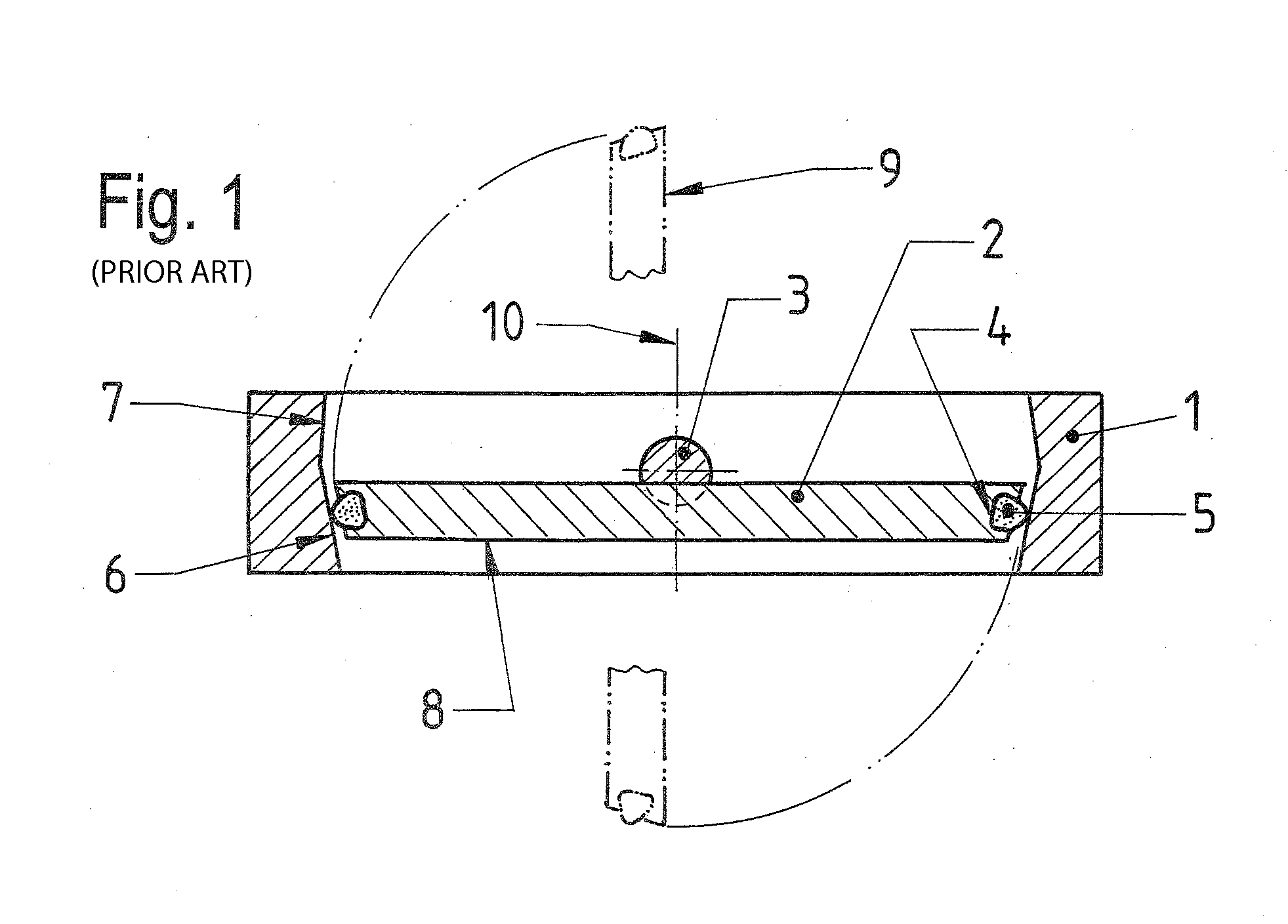
[0022]FIG. 1 shows a plate valve or also flap valve of type “butterfly” in cross section, such as has been known for a long time according to prior art. The butterfly valve is comprised of a housing part 1 with a duct opening and a single-part valve plate 2, disposed therein transversely to the opening, which plate is connected, such as for example screwed, centrally over its face with a shaft 3. The shaft 3 is disposed transversely to the housing part 1 and rotatably supported on both sides on its walls. In the valve plate 2 is sunk at the end side an encircling groove 4, into which an O-ring 5 is placed as a seal. The housing part 1 includes on the inside on both sides to the axis of the duct opening or to the direction of flow one cone 6, 7 each, which encompass the inner circumference of the housing part 1 with the duct opening and whose faces with the same and greater diameter abut one another in the form of a V. In the closed position 8 of the valve the valve plate 2 is positi...


PUM


Abstract

A valve arrangement has an annular housing with valve seat and a two-part valve plate that is rotatable about an axis. The seat is in the form of a disk including two adjacent openings with a web between and the axis is parallel to the web. The two parts of the valve plate are next to each other with their planes parallel and offset in a perpendicular direction. They are connected to each other through one of the openings by a connection piece extending through the one opening. In a closed position for the valve, the valve plate part are respectively positioned on opposite sides of the valve seat and cover and seal the respective openings due to a seal that is between the valve plate parts and the valve seat.

Description

FIELD AND BACKGROUND OF THE INVENTION[0001]The invention relates to a valve arrangement for pipe lines or containers.[0002]Valves as shut-off members for liquid and gaseous media are required in many technical areas. Depending on the given requirements, different types of valves are utilized in manifold manner. Valves close off or open pipe lines or openings on containers. Valves close off or open, for example, lines between pumps, containers, measuring apparatus and other structural parts. They permit the intake or throughflow or the shutting down of liquids or gases or they can also serve as a sluice for solid bodies. The applications of valves are highly manifold and therewith also the requirements made of their construction. Important parts of a valve are the housing and a movable plate or a valve plate, possibly with a seal, which, depending on the position, enables or shuts down passage. The valve plate is moved from the outside, the atmosphere side, and is intended to close t...

Claims


Application Information

Patent Timeline
Patent Type & Authority Applications(United States)
IPC IPC(8): F16K1/226
CPCF16K51/02F16K1/222
Inventor KELLER-STAUB, PIERINO
Owner VAT HLDG AG
Why Eureka
Try Eureka