Light emitting diode with light conversion

Inactive Publication Date: 2010-06-17
FOXSEMICON INTEGRATED TECH INC
View PDF4 Cites 29 Cited by
  • Summary
  • Abstract
  • Description
  • Claims
  • Application Information

AI Technical Summary

Problems solved by technology

However, the need to employ more than one LED makes this kind of i

Method used


Image

  • Light emitting diode with light conversion
  • Light emitting diode with light conversion
  • Light emitting diode with light conversion

Examples


first embodiment

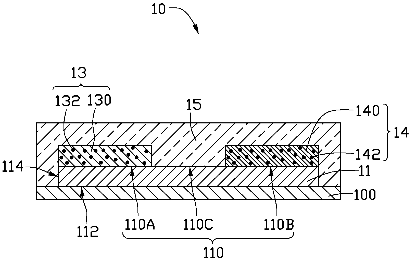
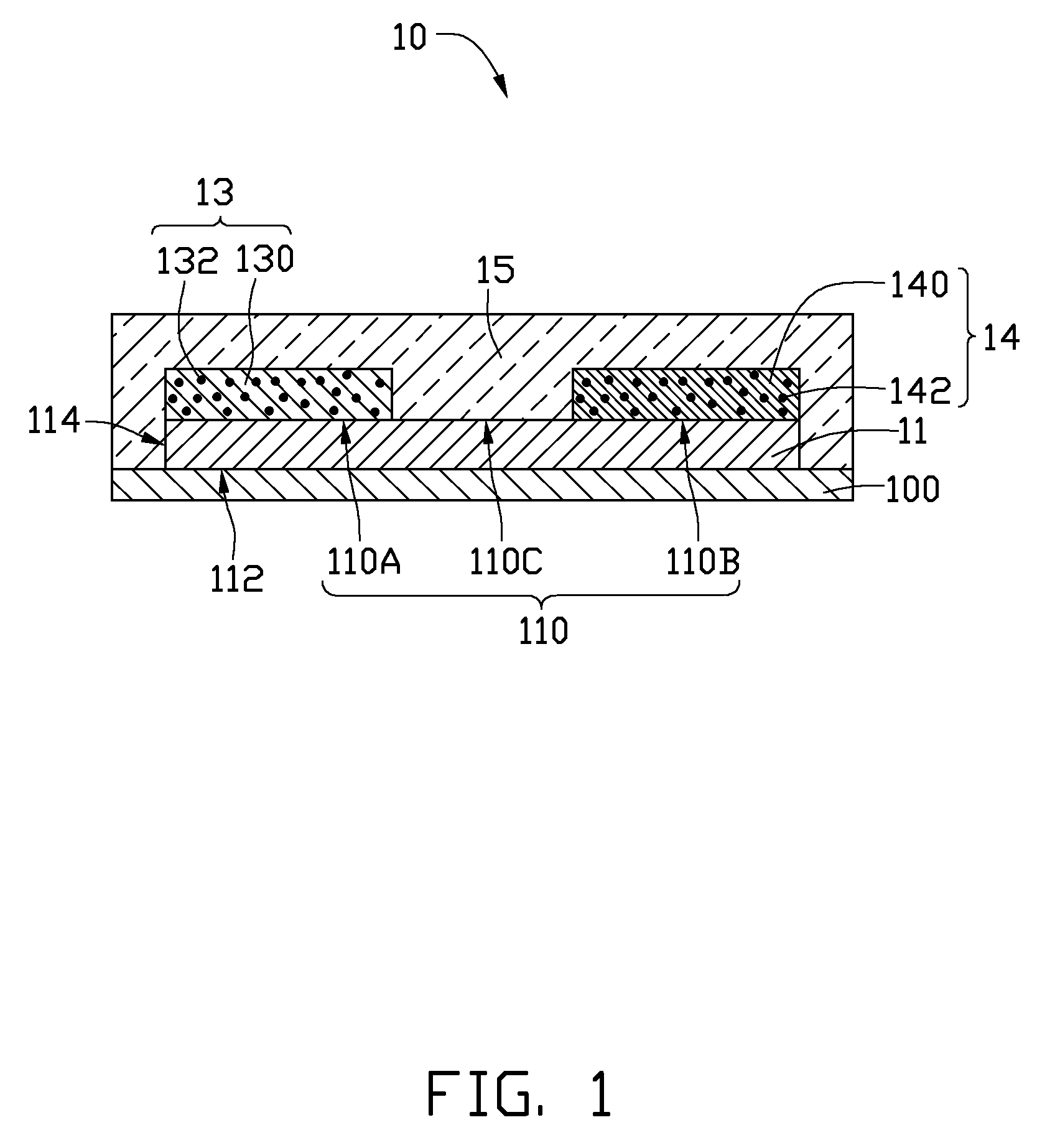
[0014]Referring to FIG. 1, an LED 10, includes an LED chip 11, a first optical wavelength converting layer 13, a second optical wavelength converting layer 14, and an encapsulant layer 15.

[0015]In the illustrated embodiment, the LED chip 11 has a prismy shape, for example, a generally cuboid shape, and is provided to emit monochromatic light. In alternative embodiments, the LED chip 11 may have a generally cylindrical shape, or a general disk shape. The monochromatic light can for example be blue light having a wavelength in a range from 410 nanometers (nm) to 490 nm, for instance 465 nm. In another example, the monochromatic light can be ultraviolet (UV) light. The LED 10 may further include a substrate 100. The substrate 100 can be used as a support on which the LED chip 11 is attached. The substrate 100 can be made of material with high thermal conductivity, such as ceramic. Heat generated by the LED chip 11 can be firstly transferred to the substrate 100, and then dissipated to...

second embodiment

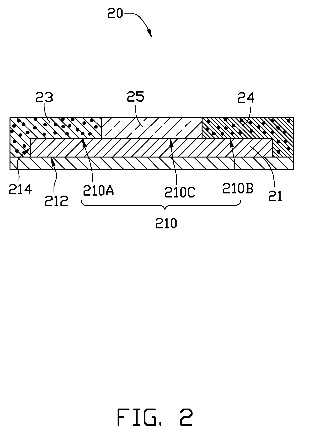
[0023]Referring to FIG. 2, an LED 20, includes an LED chip 21, a first optical wavelength converting layer 23, a second optical wavelength converting layer 24, and an encapsulant layer 25. The LED chip 21 includes a top surface 210, a bottom surface 212, and a peripheral surface 214. The top surface 210 includes a first region 210A, a second region 210B, and a third region 210C.

[0024]The LED 20 is similar to the LED 10 of the first embodiment. However, for the LED 20, the first optical wavelength converting layer 23 extends from the first region 210A to cover part of the peripheral surface 214, and the second optical wavelength converting layer 24 extends from the second region 210B to cover part of the peripheral surface 214. The first and second optical wavelength converting layers 23, 24 cooperatively cover the whole peripheral surface 214. The encapsulant layer 25 only covers the third region 210C of the top surface 210. The first and second optical wavelength converting layers...

third embodiment

[0025]Referring to FIG. 3, an LED 30, includes an LED chip 31, a first optical wavelength converting layer 33, a second optical wavelength converting layer 34, and an encapsulant layer 35. The LED chip 31 includes a top surface 310 at an upper side thereof. The top surface 310 includes a first region 310A, a second region 310B, and a third region 310C.

[0026]The LED 30 is similar to the LED 20 of the second embodiment. However, for the LED 30, a third optical wavelength converting layer 36 is further provided to cover a central part of the third region 310C. The third optical wavelength converting layer 36 includes a third base material 360, and a yellow phosphor 362 mixed in the third base material 360. In typical operation of the LED 30, the first optical wavelength converting layer 33 receives blue light from the LED chip 31, and converts the wavelength of the blue light into the wavelength of red light. The second optical wavelength converting layer 34 receives blue light from t...


PUM


Abstract

An exemplary light emitting diode includes a light emitting diode chip, two optical wavelength converting layers, and an encapsulant layer. The light emitting diode chip has an light emitting surface. The light emitting diode chip is used to emit a monochromatic light from the light emitting surface. The light emitting surface includes a first region, a second region, and a third region. The two optical wavelength converting layers covers the first and the third regions of the light emitting surface. The two optical wavelength converting layers are configured for converting the monochromatic light received from the light emitting diode chip and emitting light with a converted wavelength from the light emitting diode. The encapsulant layer covers the second region of the light emitting surface for directing light therefrom.

Description

BACKGROUND[0001]1. Technical Field[0002]The disclosure generally relates to light emitting diodes, and particularly to a light emitting diode capable of emitting light with different colors.[0003]2. Description of Related Art[0004]Nowadays, light emitting diodes (LEDs) are extensively used as light sources for illumination devices due to their high luminous efficiency, low power consumption and long lifespan. A single LED generally emits monochromatic light. A plurality of LEDs with different colors and wavelengths may be employed in a single illumination device, such that the illumination device can illuminate multicolored light. However, the need to employ more than one LED makes this kind of illumination device expensive to manufacture and costly to operate.[0005]Therefore, what is needed is a light emitting diode that overcomes the described limitations.BRIEF DESCRIPTION OF THE DRAWINGS[0006]Many aspects of the disclosure can be better understood with reference to the following ...

Claims


Application Information

Patent Timeline
IPC IPC(8): H01L33/00
CPCH01L33/20H01L33/54H01L33/508H01L33/504
Inventor LAI, CHIH-MINGJIANG, WEN-JANG
Owner FOXSEMICON INTEGRATED TECH INC
Why Eureka
Try Eureka