Eureka AIR delivers breakthrough ideas for toughest innovation challenges, trusted by R&D personnel around the world.

Imprint Mold, Imprint Apparatus and Method of Forming Pattern

Inactive Publication Date: 2010-06-17
SAMSUNG ELECTRONICS CO LTD
View PDF4 Cites 14 Cited by
  • Summary
  • Abstract
  • Description
  • Claims
  • Application Information

AI Technical Summary

Benefits of technology

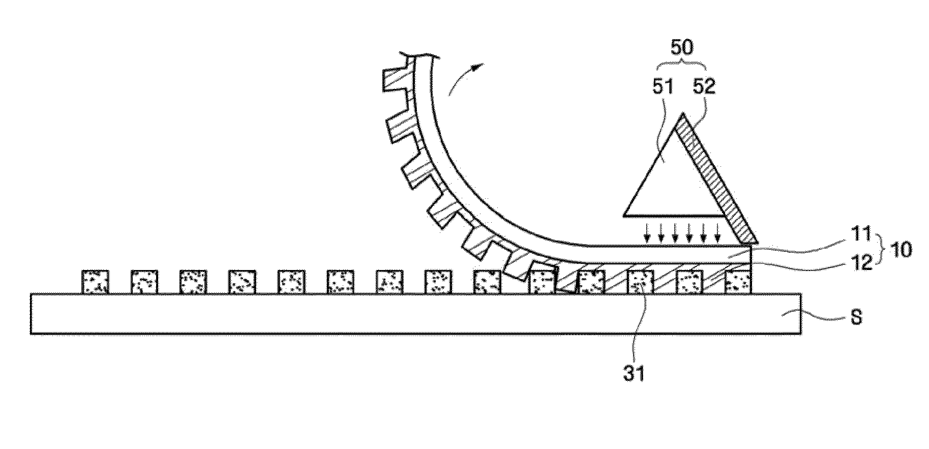
[0009]Aspects of the present invention provide an imprint mold which is substantially undeformable by heat, can achieve high precision, and can be transformed into various shapes, and an imprint apparatus including the imprint mold.
[0010]Aspects of the present invention also provide a method of forming a pattern using an imprint mold which is substantially undeformable by heat, can achieve high precision and can be transformed into various shapes.

Problems solved by technology

In recent years, the demand for flat panel displays such as a plasma display panel (PDP), a plasma-addressed liquid crystal (PALC) display, a liquid crystal display (LCD) and an organic light-emitting diode (OLED) has significantly increased because conventional cathode ray tube (CRT) devices cannot meet the demand for thin, large-scale display devices.
However, due to increases in the size of the glass substrates for forming a display device, challenges have arisen, such as increases in the costs of fabricating large-scale masks and investing in manufacturing equipment, and challenges in forming minute patterns due to wavelength limitations of the light used for exposure.
However, imprint molds using glass substrates are likely to break if deformed into other shapes.
Thus, there are restrictions on handling imprint molds using glass substrates.

Method used


Image

  • Imprint Mold, Imprint Apparatus and Method of Forming Pattern
  • Imprint Mold, Imprint Apparatus and Method of Forming Pattern
  • Imprint Mold, Imprint Apparatus and Method of Forming Pattern

Examples


Embodiment Construction

[0019]Features of embodiments of the present invention and methods of accomplishing the same may be understood more readily by reference to the following detailed description of exemplary embodiments and the accompanying drawings. Embodiments of the present invention may, however, be embodied in many different forms and should not be construed as being limited to the embodiments set forth herein. Like reference numerals refer to like elements throughout the specification.

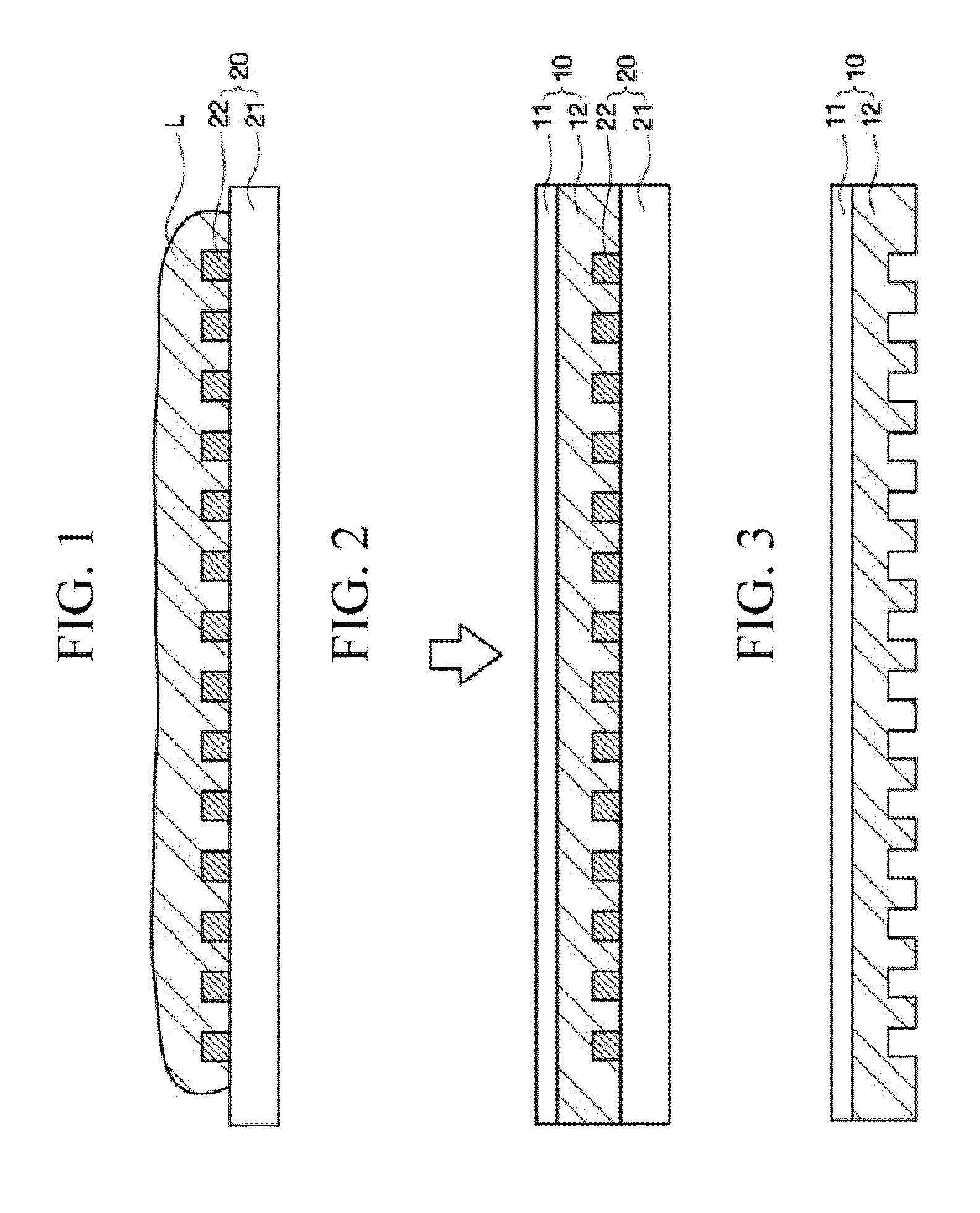
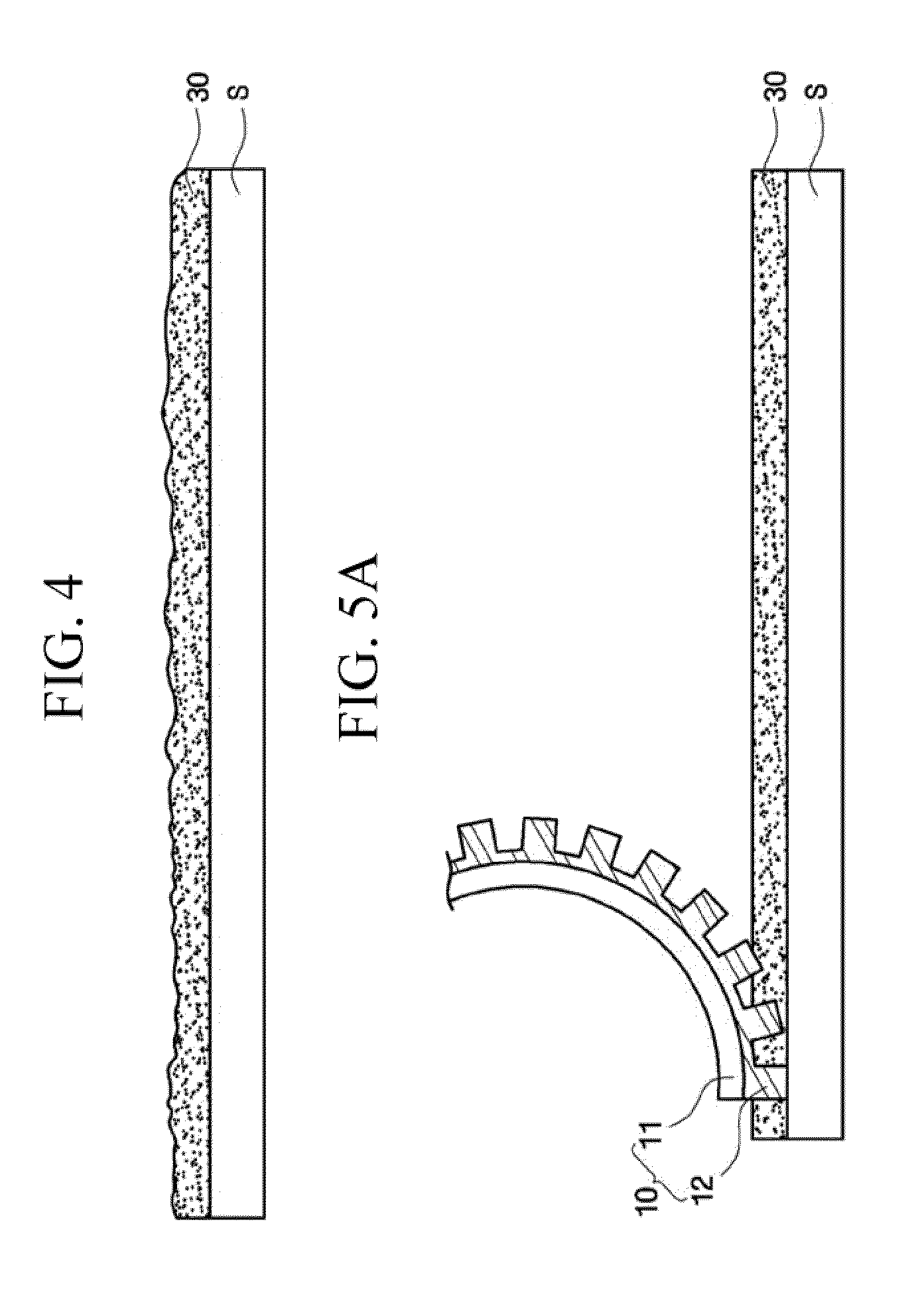
[0020]A method of manufacturing an imprint mold according to an exemplary embodiment of the present invention will hereinafter be described in detail with reference to FIGS. 1 through 3. FIGS. 1 through 3 are cross-sectional views for illustrating a method of manufacturing an imprint mold according to an exemplary embodiment of the present invention.

[0021]Referring to FIG. 1, a material L for forming a mold may be applied onto a master mold 20. The master mold 20 is a mold for forming an imprint mold 10 of FIG. 3. B...


PUM

PropertyMeasurementUnit
Temperature coefficient of resistanceaaaaaaaaaa
Flexibilityaaaaaaaaaa
Transparencyaaaaaaaaaa

Abstract

An imprint apparatus includes an imprint mold including a flexible base plate with a coefficient of thermal expansion (CTE) of about 17 ppm / ° C. or less, and a mold pattern formed on the base pattern.

Description

[0001]This application claims priority to Korean Patent Application No. 10-2008-0127321 filed on Dec. 15, 2008 in the Korean Intellectual Property Office, the contents of which are herein incorporated by reference in their entirety.BACKGROUND OF THE INVENTION[0002]1. Field of the Invention[0003]The present disclosure is directed to an imprint mold, an imprint apparatus and a method of forming a pattern, and more particularly, to an imprint mold which cannot be substantially deformed by heat, can achieve high precision, and can be transformed into various shapes, an imprint apparatus including the imprint mold and a method of forming a pattern using the imprint mold.[0004]2. Description of the Related Art[0005]In recent years, the demand for flat panel displays such as a plasma display panel (PDP), a plasma-addressed liquid crystal (PALC) display, a liquid crystal display (LCD) and an organic light-emitting diode (OLED) has significantly increased because conventional cathode ray tub...

Claims


Application Information

Patent Timeline
IPC IPC(8): B29C35/08B28B21/42B29C55/00
CPCB29C33/424B29C35/0888B29C43/222G03F7/0002B29L2031/3475B82Y10/00B82Y40/00B29C2035/0827G03F7/0017
Inventor PARK, DAE-JINKIM, KYU-YOUNGJEON, HYUNG-IL
Owner SAMSUNG ELECTRONICS CO LTD
Why Eureka
Eureka Blog
Learn More