Method and apparatus for multi-user user-specific scene visualization

Inactive Publication Date: 2010-06-17
MAMIGO
View PDF19 Cites 30 Cited by
  • Summary
  • Abstract
  • Description
  • Claims
  • Application Information

AI Technical Summary

Benefits of technology

[0015]The first aspect of this invention regards a method and apparatus for combining a first set of low-resolution, high-frame rate image sources with a second set of high-resolution, low-frame rate image sources to generate a plurality of controllable views with support for high magnification and high frame rates, in accordance with preferred embodiment of the present invention. The apparatus comprises of the first and second set of image sources, a frame grabber for the image sources, a processor for building a mathematical model that encapsulates transformation of image characteristics from lower resolution to higher resolution image sources, a View Composer for generating imagery to user-specified field of view setting, a view control device for each of the plurality of users, and a super-resolution processor that leverages the resolution transformation model to adjust, if necessary, resolution of synthesized views to the user-specified view settings. A view setting includes specification of field of view, viewpoint, view angle, resolution and frame-rate. The use of digital means for view synthesis enables a plurality of users to concurrently control their respective view settings. Further, use of high-resolution imagery to up-sample output views enables high magnification ratios. A user can virtually pan, tilt, zoom and change perspective by manipulating the view settings.
[0016]The first set of image sources can be comprised of one or more video cameras with regular or fisheye lenses, a cluster of cameras digitally processed to achieve enhanced field of view, or a catadioptric camera for enhanced field of view; and combinations thereof. The first set of image sources can be configured to have a collective field of view larger or equal to the area of interest. Alternatively, they can be configured to cover different portions of the area of interest from one or more viewpoints. Note, a portion or the whole area of interest may be imaged from one or more viewpoints. Availa

Problems solved by technology

Another example of a very high resolution but poor, frame-rate image source is a cluster of high-resolution cameras c

Method used


Image

  • Method and apparatus for multi-user user-specific scene visualization
  • Method and apparatus for multi-user user-specific scene visualization
  • Method and apparatus for multi-user user-specific scene visualization

Examples


Example

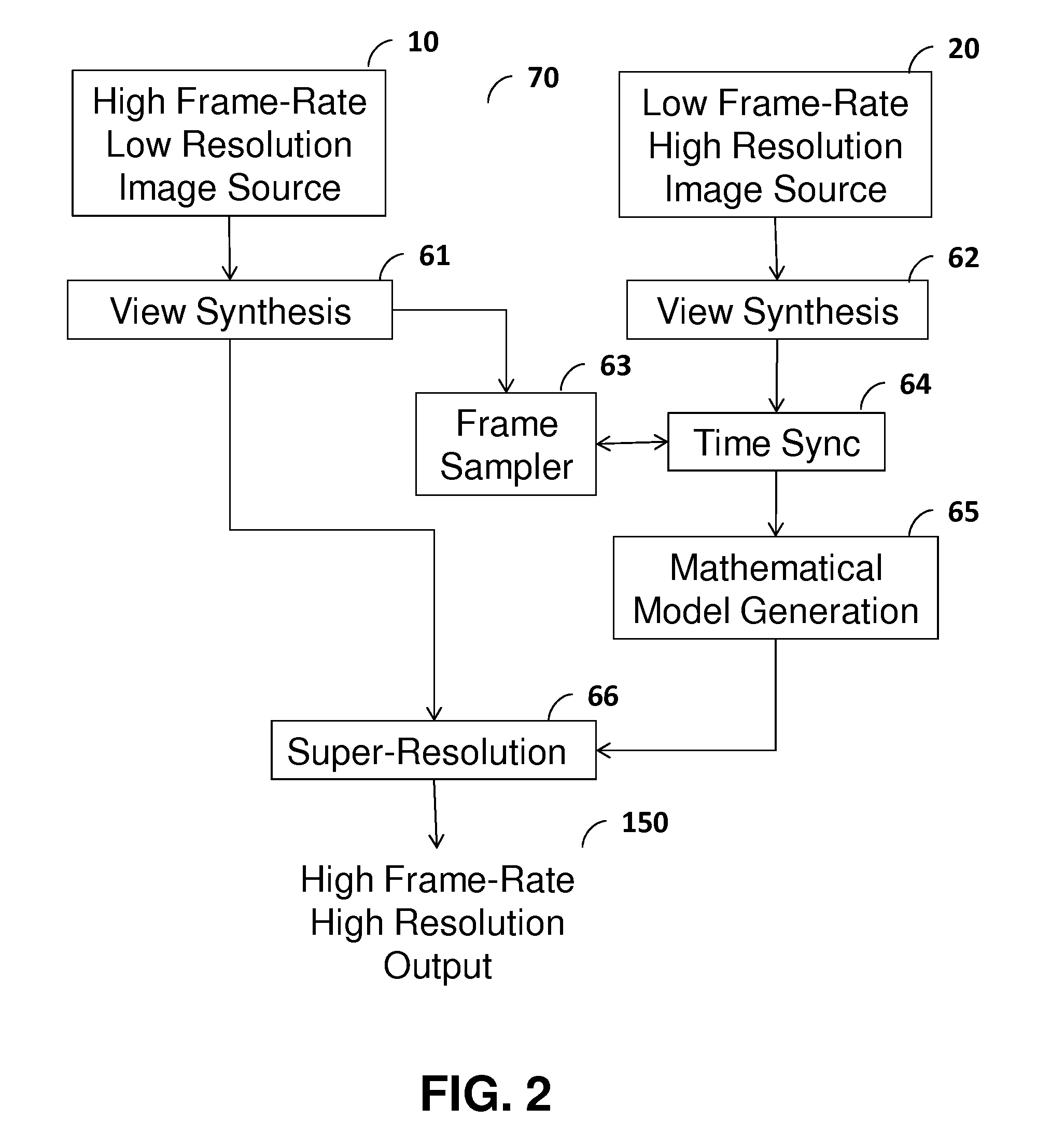
[0029]The present invention relates to a method and apparatus for providing a personalized, interactive experience of viewing a scene to a plurality of concurrent users. The key aspects of this invention relate to digitally synthesizing user-controllable views of a scene with a large magnification range using a combination of the first set of high rate, low-resolution image sources and the second set of low rate, high-resolution image sources, adaptively controlling the set of image sources and supporting a plurality of concurrent interactive users.

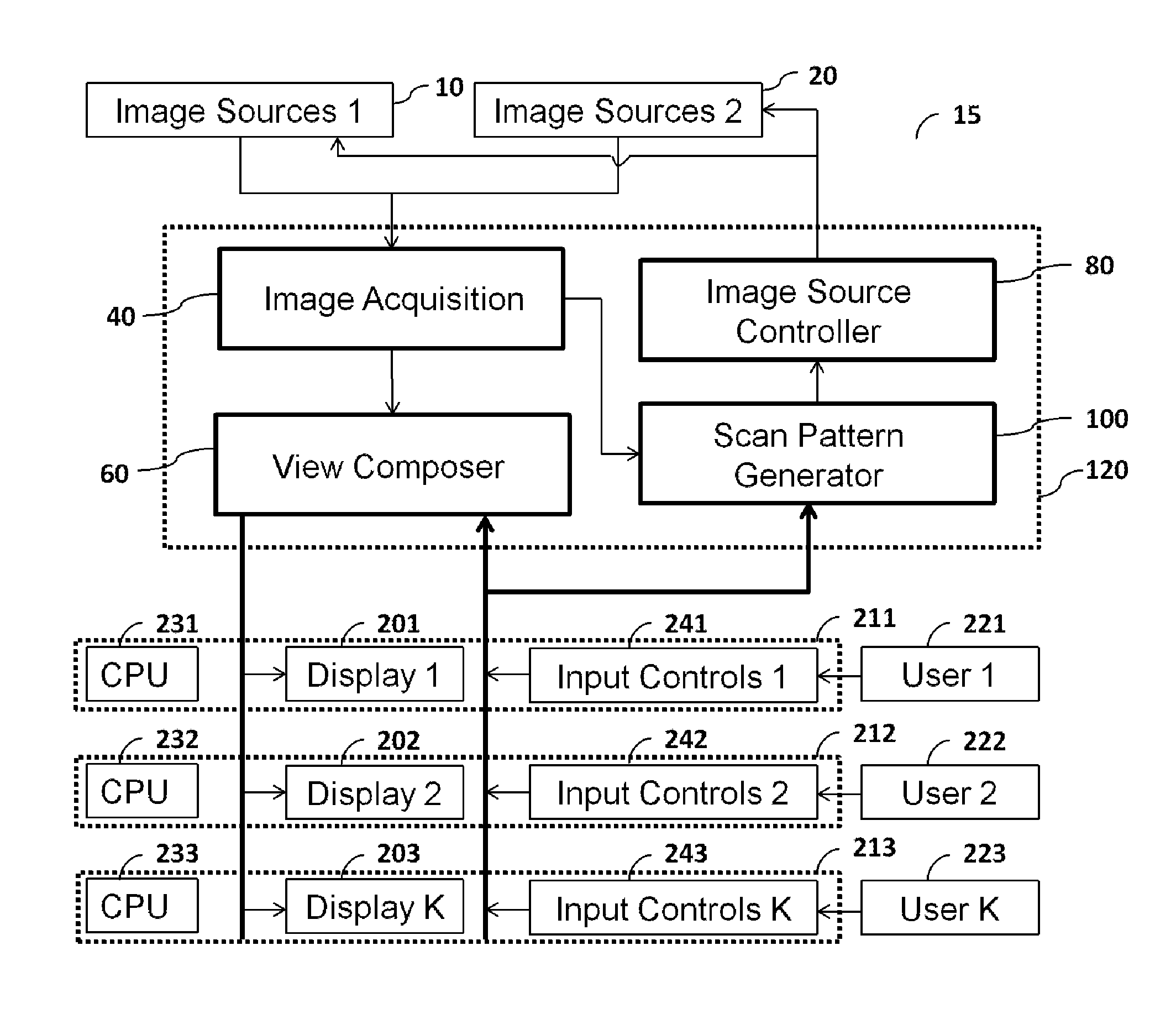
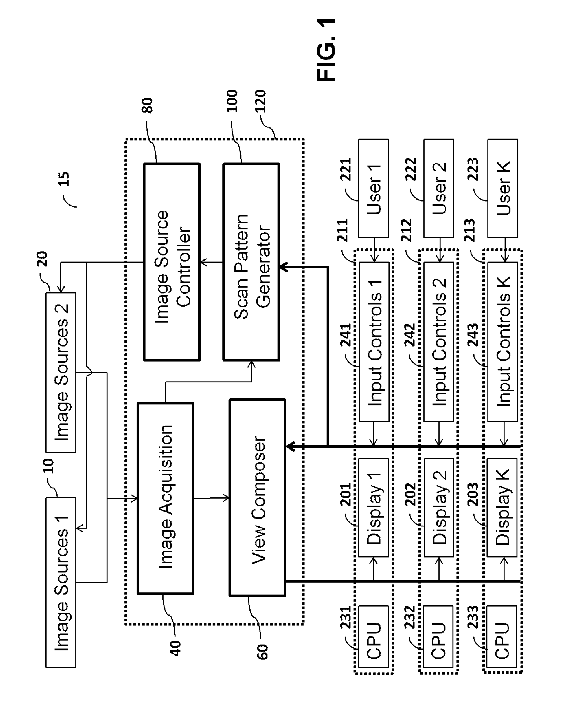
[0030]FIG. 1 is a block diagram illustrating the main components utilized by the method and apparatus for synthesizing a plurality of user-controlled views, in accordance with preferred embodiments of the present invention. The system 15 includes first set of high-frame rate, low-resolution image sources 10, and second set of low-frame rate, high-resolution image sources 20. The adjectives “high” and “low” for frame rate are used in relat...


PUM


Abstract

A method and apparatus is described for providing a personalized interactive experience to view a scene to a plurality of concurrent users. A plurality of image sources with different attributes such as frame-rate and resolution, are digitally processed to provide controllable enhanced user-specific visualization. An image source control method is also described to adjust the image sources based on collective requirement of a plurality of users.

Description

CROSS-REFERENCE TO RELATED APPLICATIONS[0001]This application claims benefit of U.S. provisional patent application Ser. No. 61 / 122,847, filed Dec. 16, 2008 which is incorporated herein as reference.BACKGROUND OF THE INVENTION[0002]1. Field of the Invention[0003]The present invention relates to a method and apparatus for providing a personalized interactive experience to view a scene with a plurality of concurrent users and, more specifically, controlling and digitally processing a plurality of image sources with different quality characteristics to synthesize user-specific views.[0004]2. Description of the Related Art[0005]Standard interactive systems limit the number of concurrent users. For example, Pan-tilt-zoom (PTZ) cameras have been used to provide users with a method to provide detailed surveillance or tracking in a wide-area surveillance scenario. These devices are normally managed by a single user at a time and sharing of the resource is not done or sharing is based on a p...

Claims


Application Information

Patent Timeline
IPC IPC(8): H04N7/18H04N5/232
CPCH04N5/2258H04N5/232H04N7/185H04N7/181H04N5/23232H04N23/45H04N23/951H04N23/631
Inventor AGGARWAL, MANOJGANTI, VIJAY
Owner MAMIGO
Why Eureka
Try Eureka