Beam-shaping device

Inactive Publication Date: 2010-06-17
KONINKLIJKE PHILIPS ELECTRONICS NV
View PDF23 Cites 68 Cited by
  • Summary
  • Abstract
  • Description
  • Claims
  • Application Information

AI Technical Summary

Benefits of technology

[0014]In view of the above-mentioned and other drawbacks of the prior art, a general object of the present invention is to provide an

Problems solved by technology

This sacrifice in resolution is unacceptable for certain applications, such as the display of small text characters for viewing from short distances.
The two-dimensional display mode cannot, of course, provide a stereoscopic image.
The resulting display is capable of providing stereoscopic images, but has the inevitable resolution loss mentioned above.
This process is not compatible with t

Method used


Image

  • Beam-shaping device
  • Beam-shaping device
  • Beam-shaping device

Examples


Embodiment Construction

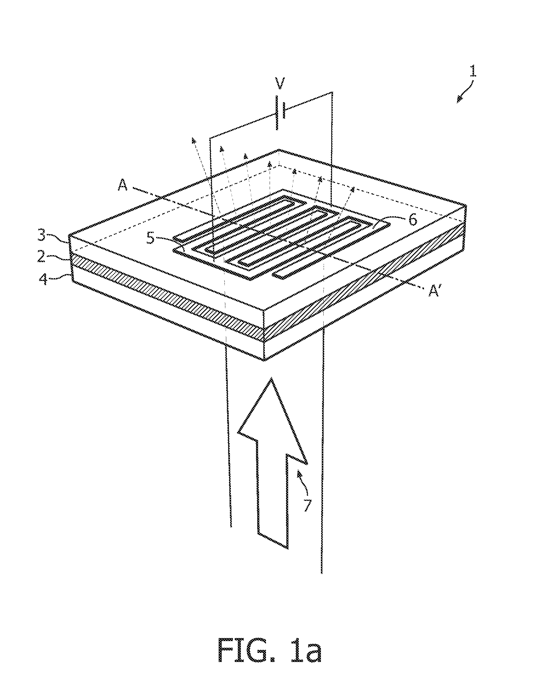
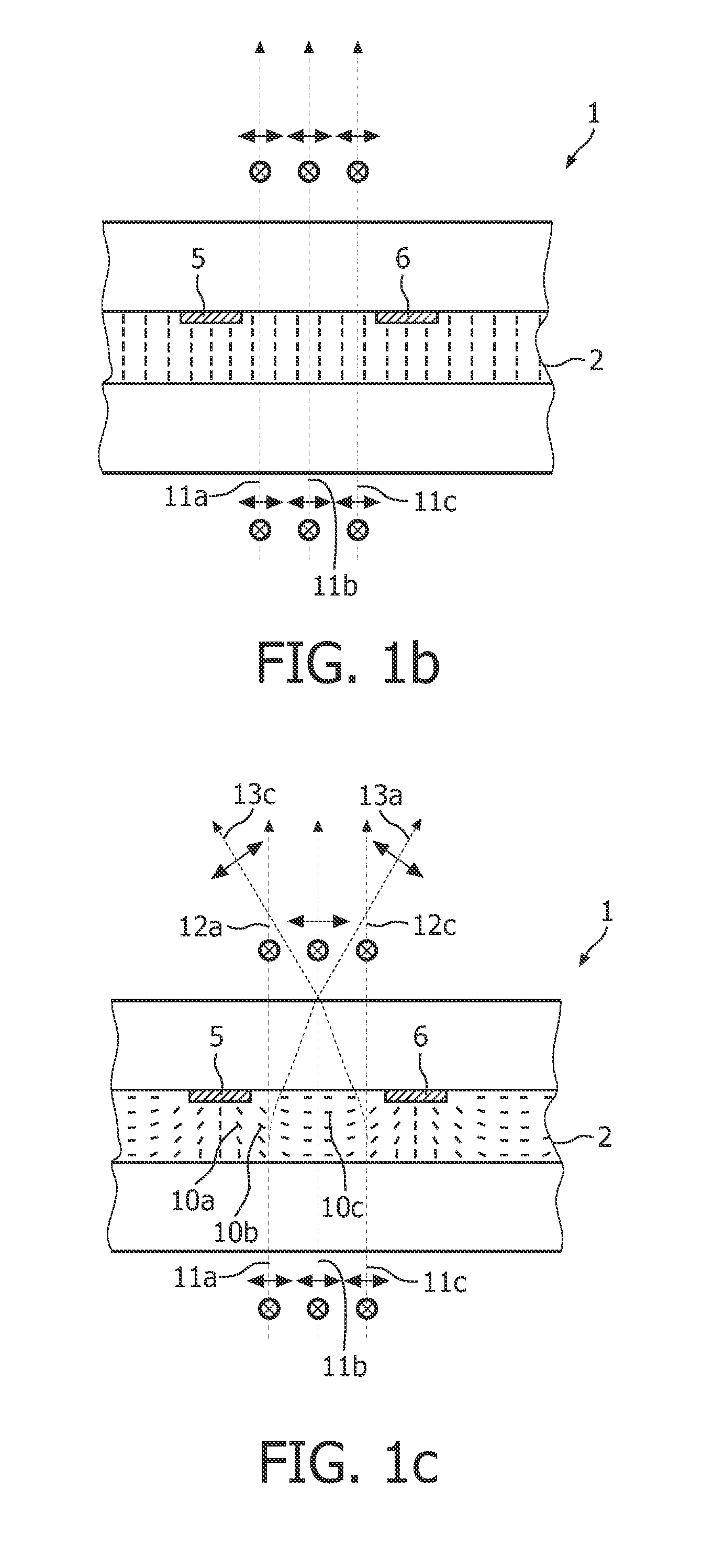
[0088]In the following description, the present invention is described with reference to a beam-shaping device having a homeotropically aligned liquid crystal layer—the liquid crystal (LC) molecules comprised in the LC layer are oriented perpendicular to the substrates when no voltage is applied to the electrodes. It should be noted that this by no means limits the scope of the present invention, which is equally applicable to beam-shaping devices in which the liquid crystal layer is aligned in any other way, such as a planar orientation in which the LC-molecules are oriented in a plane parallel with the substrates. In this orientation, the LC-molecules may be aligned in parallel with or perpendicular to the electrodes, or have a hybrid orientation where the LC molecules have a first orientation adjacent to the first substrate and a second orientation, orthogonal to the first orientation, adjacent to the second substrate.

[0089]Furthermore, in order not to obscure the present inventi...


PUM


Abstract

A beam shaping device (1; 31) comprising first (3; 33) and second (4; 37) optically transparent substrates, a liquid crystal layer (2; 36) sandwiched there between, and first (5; 34) and second (6; 35) electrodes arranged on a side of the liquid crystal layer (2; 36) facing the first substrate (3; 34). The beam shaping device (1; 31) is controllable between beam-shaping states, each permitting passage of light through the beam-shaping device in a direction perpendicular thereto. The beam shaping device (1; 31) is configured in such a way that application of a voltage (V) across the first (5; 34) and second (6; 35) electrodes results in an electric field having a portion essentially parallel to the liquid crystal layer (2; 36) in a segment thereof between neighboring portions of the electrodes (5, 6; 34; 35) and extending substantially from the first substrate (3; 34) to the second (4; 35) substrate. In this way a relatively high refractive index gradient can be obtained across short distances, which enables a very efficient beam shaping. The electric field can be achieved by utilizing electrodes provided on one side of the liquid crystal layer, in a so-called in-plane configuration. The device can be used in an autostereoscopic display device, for switching between 2D and 3D modes.

Description

TECHNICAL FIELD[0001]The present invention relates to a beam shaping device which is controllable between beam-shaping states, each permitting passage of light through the beam-shaping device in a direction perpendicular thereto.BACKGROUND OF THE INVENTION[0002]Active beam shaping is useful for various applications ranging from general lighting to special lighting applications, such as a video flash in which the zoom function of the camera is coupled to the beam width control function of an active optical element. Liquid crystal optics would appear to be suitable for this purpose. The alignment orientation of liquid crystal molecules in a liquid crystal cell can be controlled by applying an electric field thereto. This reorientation of the liquid crystal molecules results in a refractive index gradient, which leads to a light ray passing through the liquid crystal cell being redirected. Hereby, the direction and / or shape of a light beam can be controlled electrically.[0003]One appli...

Claims


Application Information

Patent Timeline
IPC IPC(8): G02F1/133G02F1/1343G02F1/1347G02F1/13357G02F1/1333G02F1/1335
CPCG02B27/225H04N13/0454G02F1/29G02F1/134363H04N13/359G02F1/134381G02F1/134372G02B30/26
Inventor HIKMET, RIFAT ATA MUSTAFAVAN BOMMEL, TIESKRAAN, THOMAS CASPARKUSTERS, LEON HENDRIKUS CHRISTIAANDE ZWART, SIEBE TJEKWILLEMSEN, OSCAR HENDRIKUSKRIJN, MARCELLINUS PETRUS CAROLUS MICHAEL
Owner KONINKLIJKE PHILIPS ELECTRONICS NV
Why Eureka
Try Eureka