Method for Determining a Time Delay for Time Delay Compensation

a time delay and compensation technology, applied in direction/deviation determination systems, direction finders using ultrasonic/sonic/infrasonic waves, instruments, etc., can solve the problem of computational inefficiency of frequent re-calculation, and achieve the effect of time delay compensation

Active Publication Date: 2010-06-17
CERENCE OPERATING CO
View PDF2 Cites 69 Cited by
  • Summary
  • Abstract
  • Description
  • Claims
  • Application Information

AI Technical Summary

Benefits of technology

[0011]In certain embodiments, the beamformer arrangement may include internally or externally residual echo cancellation logic. If the predetermined criterion is fulfilled, the residual echo cancellation

Problems solved by technology

This time delay originates from a signal propagation delay due to the relative positioning of a wanted sound source

Method used


Image

  • Method for Determining a Time Delay for Time Delay Compensation
  • Method for Determining a Time Delay for Time Delay Compensation
  • Method for Determining a Time Delay for Time Delay Compensation

Examples


Embodiment Construction

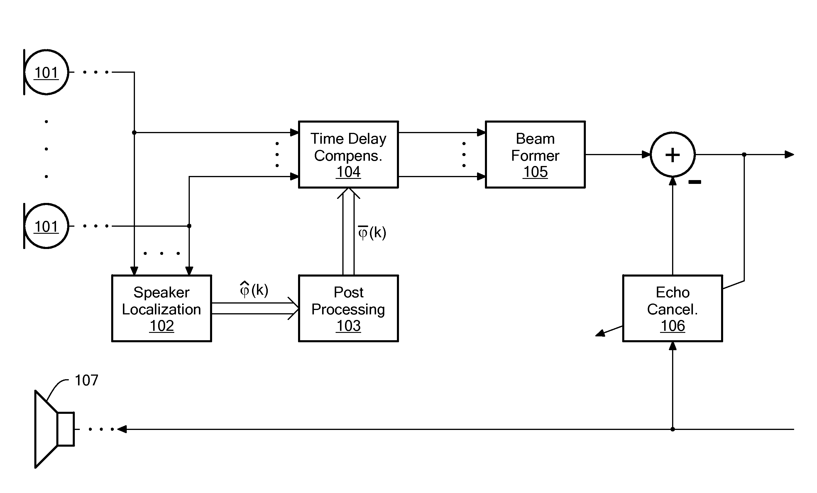
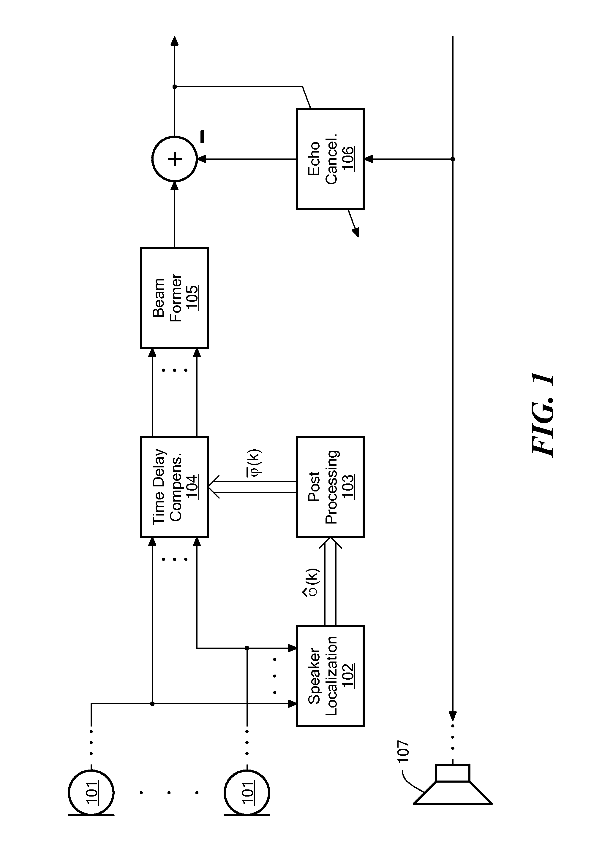
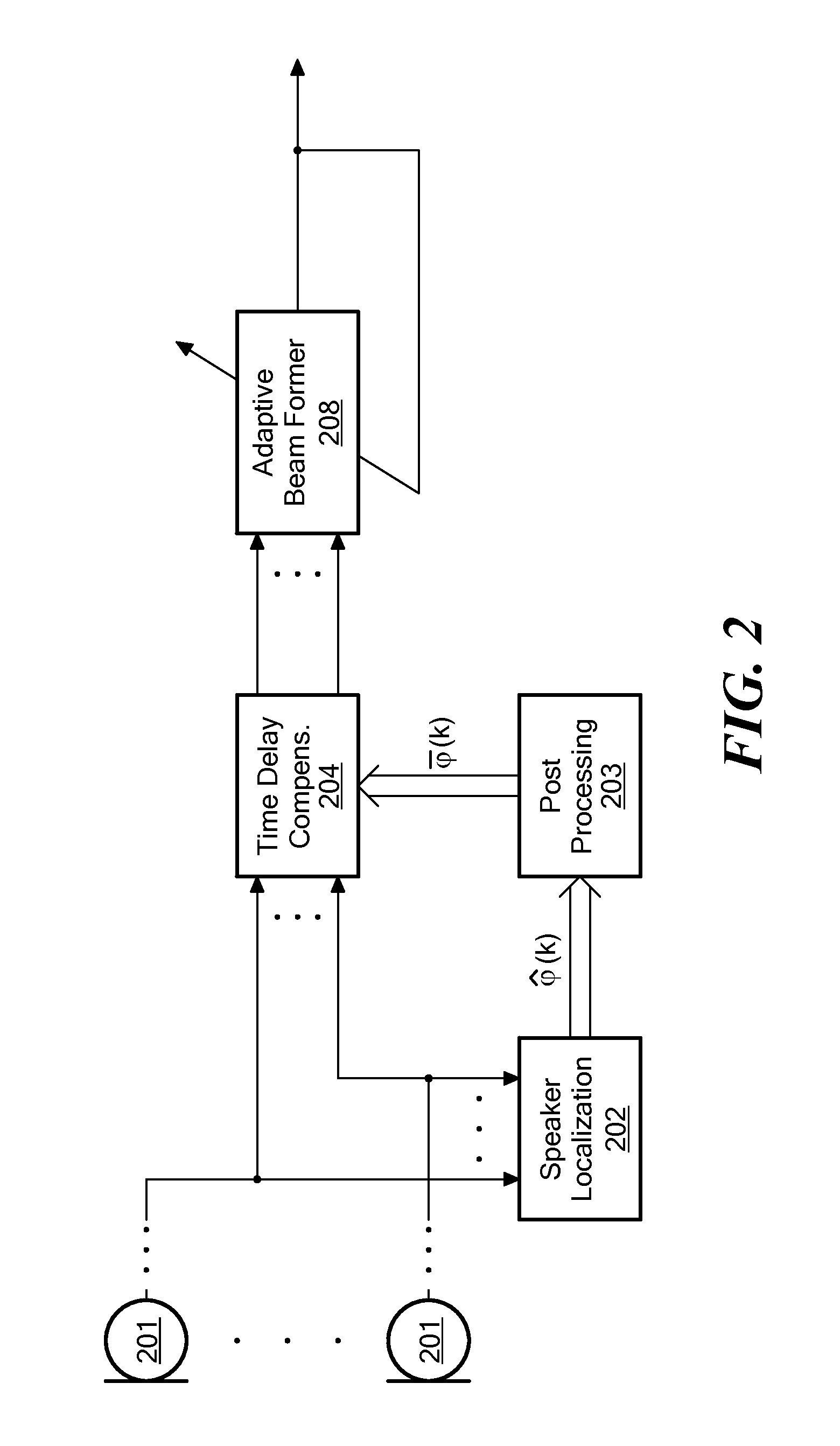
[0020]Embodiments of the present invention provide a method and a system for determining computationally more efficient a time delay for time delay compensation of a microphone signal from a microphone array in a beamformer arrangement. The methodology and system may be embodied within a speech processing system having one or more processors for performing the disclosed methodology. Further, the time delay compensation determination may be embodied in hardware logic such as a circuit or an integrated circuit (e.g. an application specific integrated circuit) or in a field programmable gate array (FPGA). The methodology may be embodied as hardware logic or software logic or a combination thereof. In the software embodiments or partial software embodiments, the computer software will be embodied on a tangible computer readable storage medium i.e. a computer program product. The computer program product is operable in conjunction with a processor that executes the computer code thereon....


PUM


Abstract

The invention provides a computer-implemented method for determining a time delay for time delay compensation of a microphone signal from a microphone array in a beamformer arrangement. For a given time, an instantaneous estimate of a position of a wanted sound source and/or of a direction of arrival of a signal originating from the wanted sound source is determined. The computer system then determines whether the instantaneous estimate deviates from a preset estimate of a position of the wanted sound source and/or of a direction of arrival of a signal originating from the wanted sound source according to a predetermined criterion. The predetermined criterion comprises a check whether the instantaneous estimate deviates from the preset estimate by at least a predetermined deviation threshold. If the predetermined criterion is fulfilled, the instantaneous estimate for the given time is set by the computer system as the preset estimate, and the computer system determines the time delay for time delay compensation of the microphone signal based on the instantaneous estimate.

Description

PRIORITY [0001]The present U.S. patent application claims priority from European Patent Application No. 08 021 682.3 entitled Method for Determining a Time Delay for Time Delay Compensation filed on Dec. 12, 2008, which is incorporated herein by reference in its entirety.TECHNICAL FIELD [0002]The present invention relates to a method for determining a time delay for time delay compensation of a microphone signal from a microphone array in a beamformer arrangement.BACKGROUND ART [0003]The main purpose of a beamformer arrangement is to process acoustic signals in such a way, that signals from a preferred direction are enhanced with respect to signals from other directions. In this way, the signal quality of signals originating from a wanted sound source can be enhanced while noise, originating from different positions or directions of arrival, is reduced or even completely cancelled.[0004]Such systems, an example is known from EP 1 640 971, are used, for instance, for hands-free commu...

Claims


Application Information

Patent Timeline
IPC IPC(8): H04B3/20H04R3/00
CPCG01S3/807G10L21/02H04M9/082H04R1/406H04R3/005H04S3/00H04R2410/01H04R2430/23H04R2430/25H04R2499/13H04S1/00H04R3/02
Inventor BUCK, MARKUSWOLFF, TOBIASSCHMIDT, GERHARDHAULICK, TIM
Owner CERENCE OPERATING CO
Why Eureka
Try Eureka