Supercharge Your Innovation With Domain-Expert AI Agents!

Construction method of solar battery modules

a solar battery module and construction method technology, applied in the direction of heat collector mounting/support, pv power plants, light and heating equipment, etc., can solve the problems of deterioration of the fixing strength and achieve the effect of preventing the main body of the solar battery module from disconnecting, reducing labor required for mounting the solar battery module, and preventing the disconnection of the solar battery modul

Active Publication Date: 2010-06-24
YANEGIJUTSUKENKYUJO CO LTD
View PDF4 Cites 7 Cited by
  • Summary
  • Abstract
  • Description
  • Claims
  • Application Information

AI Technical Summary

Benefits of technology

[0010]According to the present invention, the position of the fixing member can freely be moved with respect to the first frame body. Therefore, when fixed to a roofboard of a roof as the support member, the fixing member can be slid and mounted into a position where there is a structure member such as a rafter which supports the roofboard at predetermined intervals, and thereby can be mounted more securely, which enables the solar battery module to be fixed more securely. Since the first frame bodies adjacent to each other across an axis between the pedestal and the to-be connected portion are connected with each other, the adjacent two first frame bodies can be fixed by the fixing member, the labor required for mounting the solar battery module can be reduced, and any solar battery module can be fixed to the support member.
[0017]According to the present invention, a construction method of solar battery modules that can be more securely fixed by a fixing member for fixing solar battery modules can be provided.

Problems solved by technology

Therefore, in some cases the position of the rafters which support the roofboard 31 at predetermined intervals and the position of the joint portion 62 of the solar battery module are not aligned with each other, which creates problems such as the joint portion 62 not being fixed to the rafter and the deterioration of the fixing strength of the solar battery module.

Method used


Image

  • Construction method of solar battery modules
  • Construction method of solar battery modules
  • Construction method of solar battery modules

Examples


Embodiment Construction

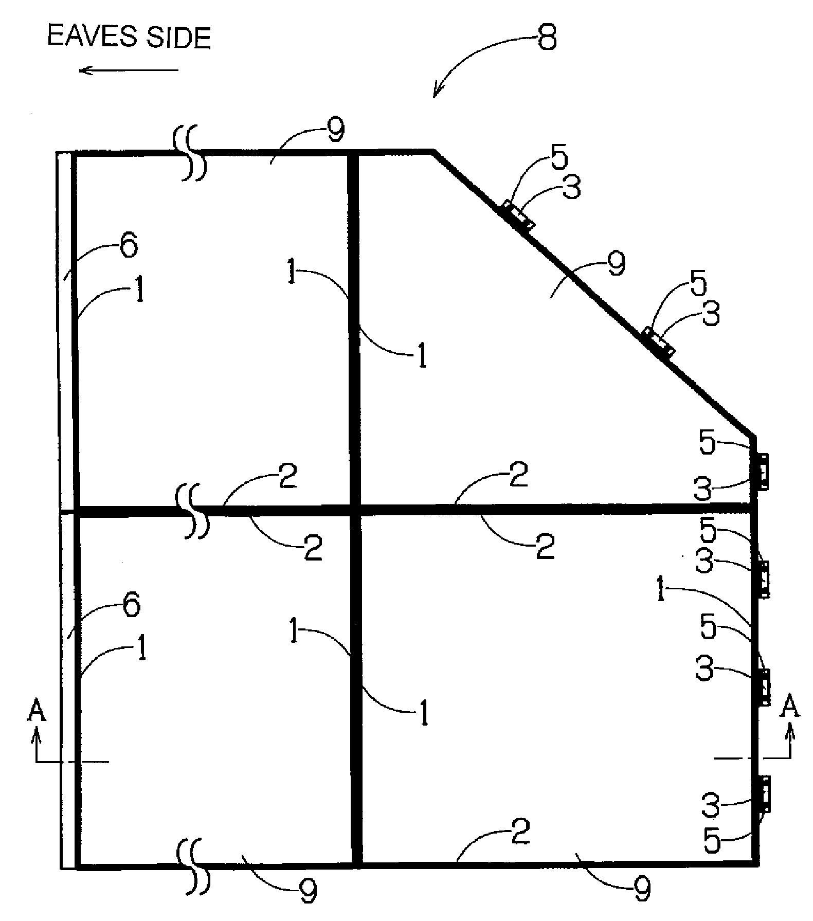
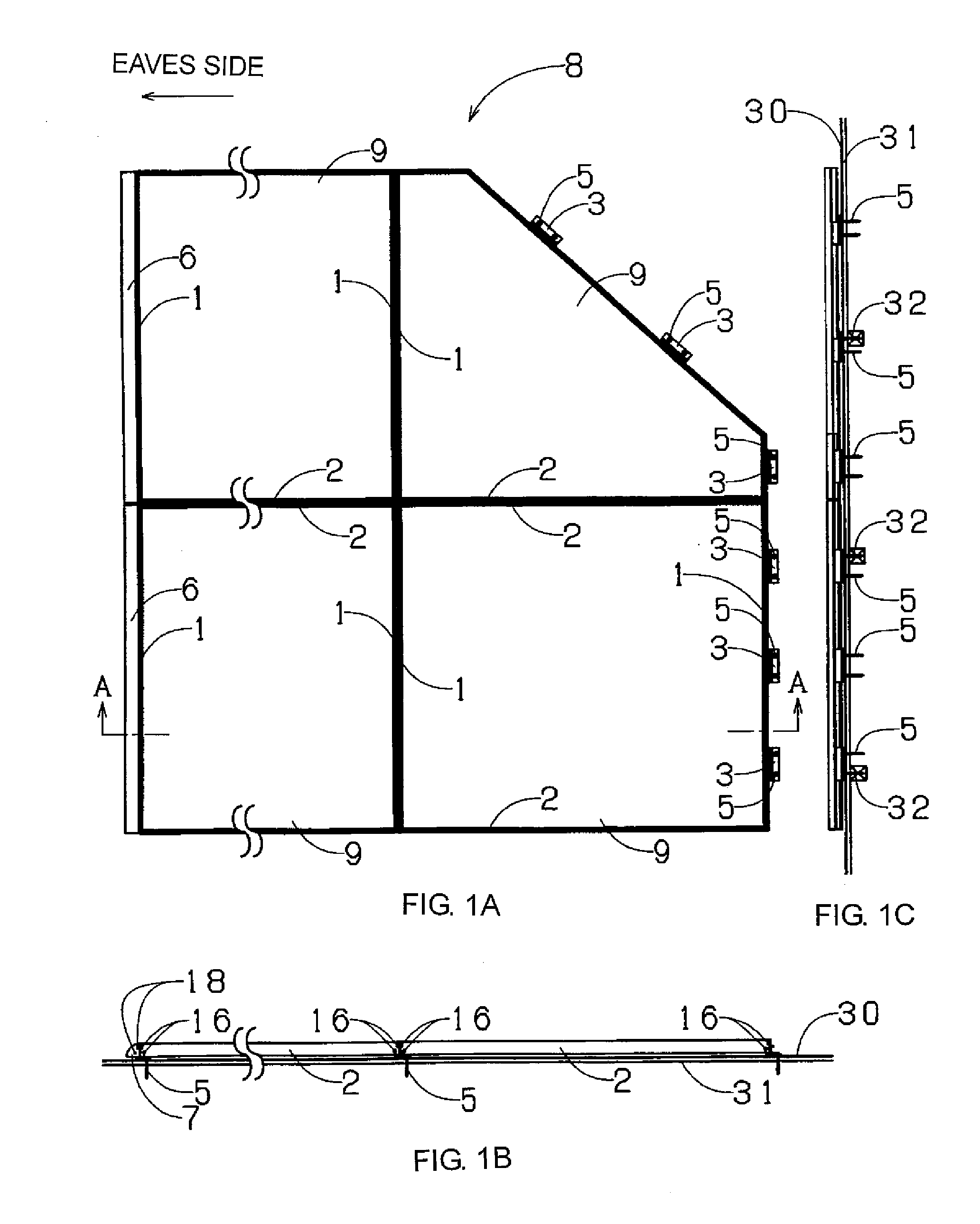
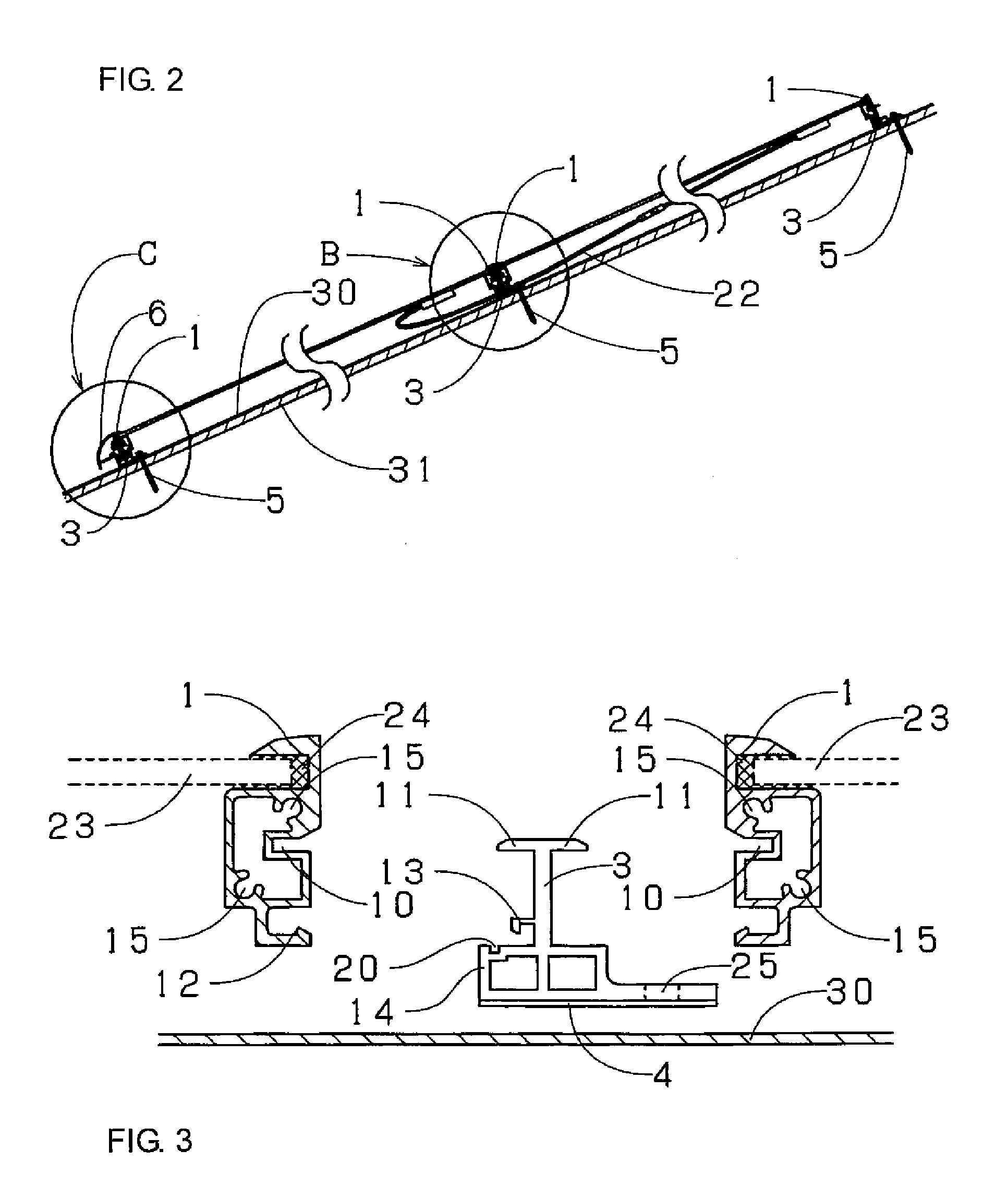
[0034]An embodiment of a solar battery module frame body which is the best mode for carrying out the invention will be explained based on the drawings. FIG. 1A is a schematic plan view showing a state where a solar battery module frame body of an embodiment of the present invention is disposed, FIG. 1B is a right side view of FIG. 1A and FIG. 1C is a rear view of FIG. 1A. FIG. 2 is a sectional view used for explaining the portion of the line A-A in FIG. 1 in detail. FIG. 3 is an exploded sectional view of various parts of the solar battery module frame body in FIG. 1. FIG. 4 is a sectional view showing the portion B in FIG. 2 in detail. FIGS. 5 to 7 are enlarged views of an essential portion of the solar battery module frame body in FIG. 2 and are schematic sectional views showing procedure. FIG. 8 is a sectional view used for explaining the portion C in FIG. 2 in detail. FIG. 9 is a perspective view showing the portion B in FIG. 2.

[0035]As shown in FIGS. 1, according to the solar b...


PUM

PropertyMeasurementUnit
fixing strengthaaaaaaaaaa
shapesaaaaaaaaaa
shapeaaaaaaaaaa

Abstract

A construction method of solar battery modules by which solar battery modules are fixed using a fixing member, including: connecting a first frame body of a solar battery module between a pedestal and a to-be connected portion on a side opposite to a side of a plate-like portion extending outward farther than the pedestal with respect to an axis of the fixing member; sliding the fixing member to a position of a structural member such as a rafter along the first frame body; fixing the fixing member to a support member by the plate-like portion extending outward farther than the pedestal; and connecting a first frame body of a second solar battery module different from the first solar battery module between the pedestal and the to-be connected portion on a side identical to a side of the plate-like portion extending outward farther than the pedestal with respect to the axis.

Description

CROSS REFERENCE TO RELATED APPLICATIONS[0001]This is a divisional application of application Ser. No. 11 / 536,000 filed on Sep. 28, 2006, which claims priority upon Japanese Patent Application No. 2005-358534 filed on Dec. 13, 2005, of which are herein incorporated by reference.BACKGROUND OF THE INVENTION[0002]1. Field of the Invention[0003]The present invention relates to a construction method of solar batter modules.[0004]2. Background of the Invention[0005]A conventional solar battery module can be mounted directly on a roofboard without the use of a roofing agent. As shown in FIG. 10, frame bodies of two solar battery modules are adjacent in a flowing direction and a vertical direction, a joint portion 62 formed on a ridge-side frame body 61 of an eaves-side solar battery module is connected to a roofboard 31, and a ridge-side fitting portion 64 formed on a ridge-side frame body 61 of an eaves-side solar battery module is fitted into an eaves-side fitting portion 63 formed on an ...

Claims


Application Information

Patent Timeline
Patent Type & Authority Applications(United States)
IPC IPC(8): H05K13/00
CPCF24J2/5211F24J2/5245F24J2/5262F24J2002/4661Y10T29/49002Y02B10/20Y02E10/47H02S20/23Y02B10/12F24S25/61F24S25/20F24S2025/6002F24S25/67Y02E10/50Y02B10/10H01L31/042H02S20/20
Inventor KOBAYASHI, SHUICHI
Owner YANEGIJUTSUKENKYUJO CO LTD
Features
  • R&D
  • Intellectual Property
  • Life Sciences
  • Materials
  • Tech Scout
  • Unparalleled Data Quality
  • Higher Quality Content
  • 60% Fewer Hallucinations
Learn More