Supercharge Your Innovation With Domain-Expert AI Agents!

Fixing member of solar battery modules

a solar battery module and fixing member technology, applied in the direction of solar thermal energy generation, solar heating energy, heat collector mounting/support, etc., can solve the problems of deterioration of the fixing strength of reduce the labor required for mounting the solar battery module, and prevent the main body from being damaged

Active Publication Date: 2010-06-24
YANEGIJUTSUKENKYUJO CO LTD
View PDF7 Cites 16 Cited by
  • Summary
  • Abstract
  • Description
  • Claims
  • Application Information

AI Technical Summary

Benefits of technology

The present invention provides a fixing member for solar battery modules that can securely fix the modules to a support member, such as a roof, while also allowing for easy movement and positioning during installation. The fixing member includes a to-be connected portion, a pedestal, and a portion connecting the to-be connected portion and the pedestal. The fixing member also includes a plate-like portion that extends farther out than the pedestal and is designed to support the modules and reduce labor during installation. The fixing member can be easily attached to the support member using screws or other fasteners. The technical effects of the invention include reducing labor required for mounting the solar battery module, ensuring consistent appearance with the surrounding environment, and facilitating installation.

Problems solved by technology

Therefore, in some cases the position of the rafters which support the roofboard 31 at predetermined intervals and the position of the joint portion 62 of the solar battery module are not aligned with each other, which creates problems such as the joint portion 62 not being fixed to the rafter and the deterioration of the fixing strength of the solar battery module.

Method used


Image

  • Fixing member of solar battery modules
  • Fixing member of solar battery modules
  • Fixing member of solar battery modules

Examples


Embodiment Construction

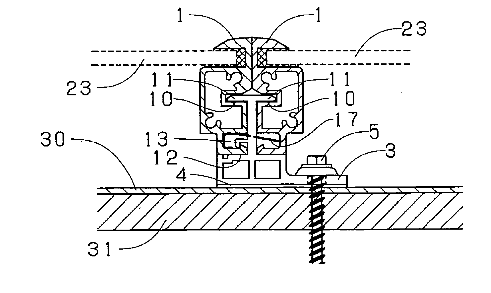
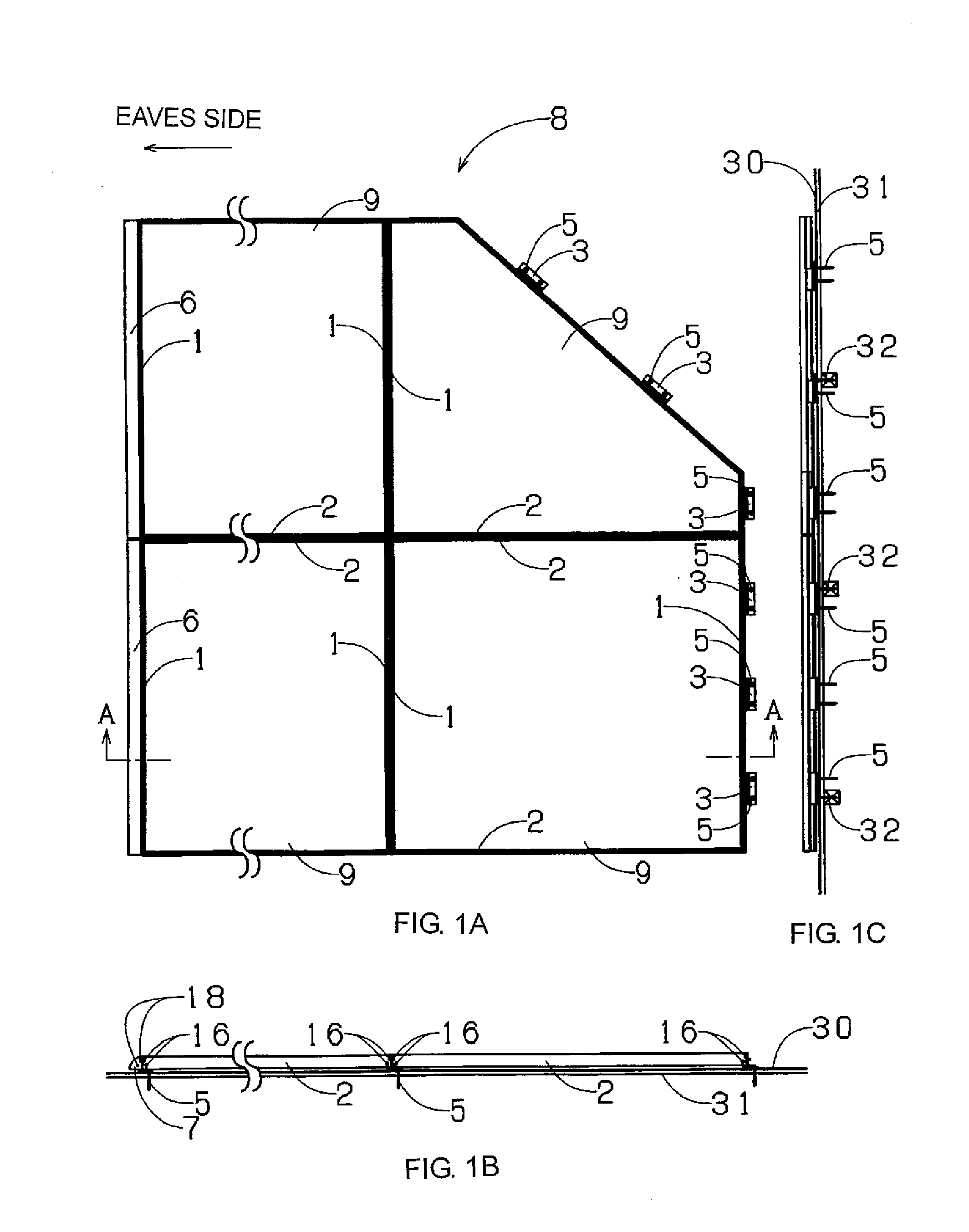
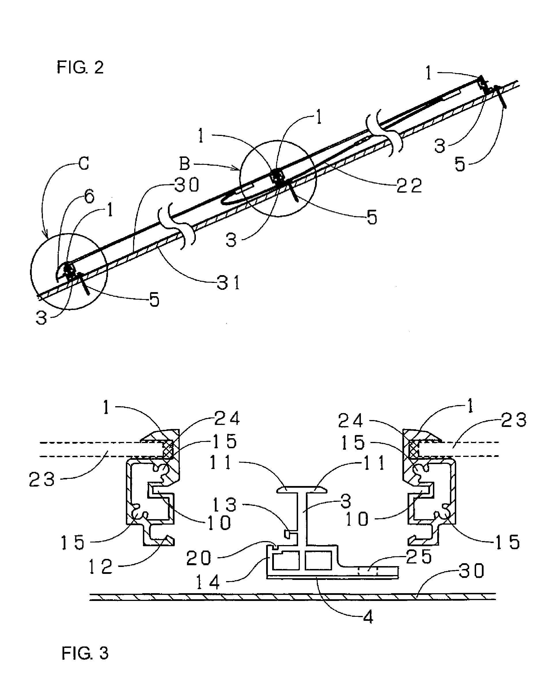
[0033]An embodiment of a solar battery module frame body which is the best mode for carrying out the invention will be explained based on the drawings. FIG. 1A is a schematic plan view showing a state where a solar battery module frame body of an embodiment of the present invention is disposed, FIG. 1B is a right side view of FIG. 1A and FIG. 1C is a rear view of FIG. 1A. FIG. 2 is a sectional view used for explaining the portion of the line A-A in FIG. 1 in detail. FIG. 3 is an exploded sectional view of various parts of the solar battery module frame body in FIG. 1. FIG. 4 is a sectional view showing the portion B in FIG. 2 in detail. FIGS. 5 to 7 are enlarged views of an essential portion of the solar battery module frame body in FIG. 2 and are schematic sectional views showing procedure. FIG. 8 is a sectional view used for explaining the portion C in FIG. 2 in detail. FIG. 9 is a perspective view showing the portion B in FIG. 2.

[0034]As shown in FIG. 1, according to the solar ba...


PUM

PropertyMeasurementUnit
fixing strengthaaaaaaaaaa
shapesaaaaaaaaaa
movementaaaaaaaaaa

Abstract

A fixing member of solar battery modules for fixing edges of module glass to a roofboard by solar battery modules supporting a first frame body, including: a to-be connected portion to restrict the first frame body from moving upward; a pedestal to restrict the first frame body from moving downward; a portion connecting the pedestal and to-be connected portion to restrict solar battery modules from moving in a direction perpendicular to a longitudinal direction of the first frame body and outwardly along a surface of solar battery modules; and a plate-like portion extending outward farther than one side of the pedestal, the fixing member being fixed to the roofboard through the plate-like portion, supported on both sides of the portion connecting the pedestal and to-be connected portion such that upper surfaces of adjacent solar battery modules are substantially flush with each other, and slidable along the first frame body.

Description

CROSS REFERENCE TO RELATED APPLICATIONS[0001]This is a divisional application of application Ser. No. 11 / 536,000 filed on Sep. 28, 2006, which claims priority upon Japanese Patent Application No. 2005-358534 filed on Dec. 13, 2005, of which are herein incorporated by reference.BACKGROUND OF THE INVENTION[0002]1. Field of the Invention[0003]The present invention relates to a fixing member of solar battery modules.[0004]2. Background of the Invention[0005]A conventional solar battery module can be mounted directly on a roofboard without the use of a roofing agent. As shown in FIG. 10, frame bodies of two solar battery modules are adjacent in a flowing direction and a vertical direction, a joint portion 62 formed on a ridge-side frame body 61 of an eaves-side solar battery module is connected to a roofboard 31, and a ridge-side fitting portion 64 formed on a ridge-side frame body 61 of an eaves-side solar battery module is fitted into an eaves-side fitting portion 63 formed on an eaves...

Claims


Application Information

Patent Timeline
Patent Type & Authority Applications(United States)
IPC IPC(8): F16M11/04
CPCF24J2/5211F24J2/5245F24J2/5262F24J2002/4661Y10T29/49002Y02B10/20Y02E10/47H02S20/23Y02B10/12F24S25/61F24S25/20F24S2025/6002F24S25/67Y02E10/50Y02B10/10H01L31/042H02S20/20
Inventor KOBAYASHI, SHUICHI
Owner YANEGIJUTSUKENKYUJO CO LTD
Features
  • R&D
  • Intellectual Property
  • Life Sciences
  • Materials
  • Tech Scout
  • Unparalleled Data Quality
  • Higher Quality Content
  • 60% Fewer Hallucinations
Learn More