Method and apparatus for compressing a mat in exhaust gas cleaning device

a technology of exhaust gas cleaning device and mat, which is applied in the direction of mechanical equipment, machines/engines, other domestic objects, etc., to achieve the effect of simple configuration and reduced manufacturing costs of apparatus

Active Publication Date: 2010-06-24
YUTAKA GIKEN CO LTD
View PDF13 Cites 8 Cited by
  • Summary
  • Abstract
  • Description
  • Claims
  • Application Information

AI Technical Summary

Benefits of technology

[0018]Furthermore, apparatus manufacturing costs can be reduced because the mat compression apparatus has a simple configuration whose main elements include a plurality of pressers, a primary drive mechanism for causing only the odd-numbered pressers to move forward, and a secondary drive mechanism for causing only the even-numbered pressers to move forward.
[0019]A first presser for pressing end portions of the mat may be included in the odd-numbered pressers. In this manner, the end portions of the mat are initially pressed, whereby the end portions of the mat can be prevented from springing upward and being damaged.
[0020]In a preferred form, two ends of the even-numbered pressers are divided in parallel to respective movement axes. Consequently, the gap between adjoining pressers can be kept constant. There is no concern that the mat will become wedged by the adjoining pressers because the gap does not vary.

Problems solved by technology

First, only the odd-numbered pressers are caused to move forward to compress the mat.

Method used


Image

  • Method and apparatus for compressing a mat in exhaust gas cleaning device
  • Method and apparatus for compressing a mat in exhaust gas cleaning device
  • Method and apparatus for compressing a mat in exhaust gas cleaning device

Examples


Embodiment Construction

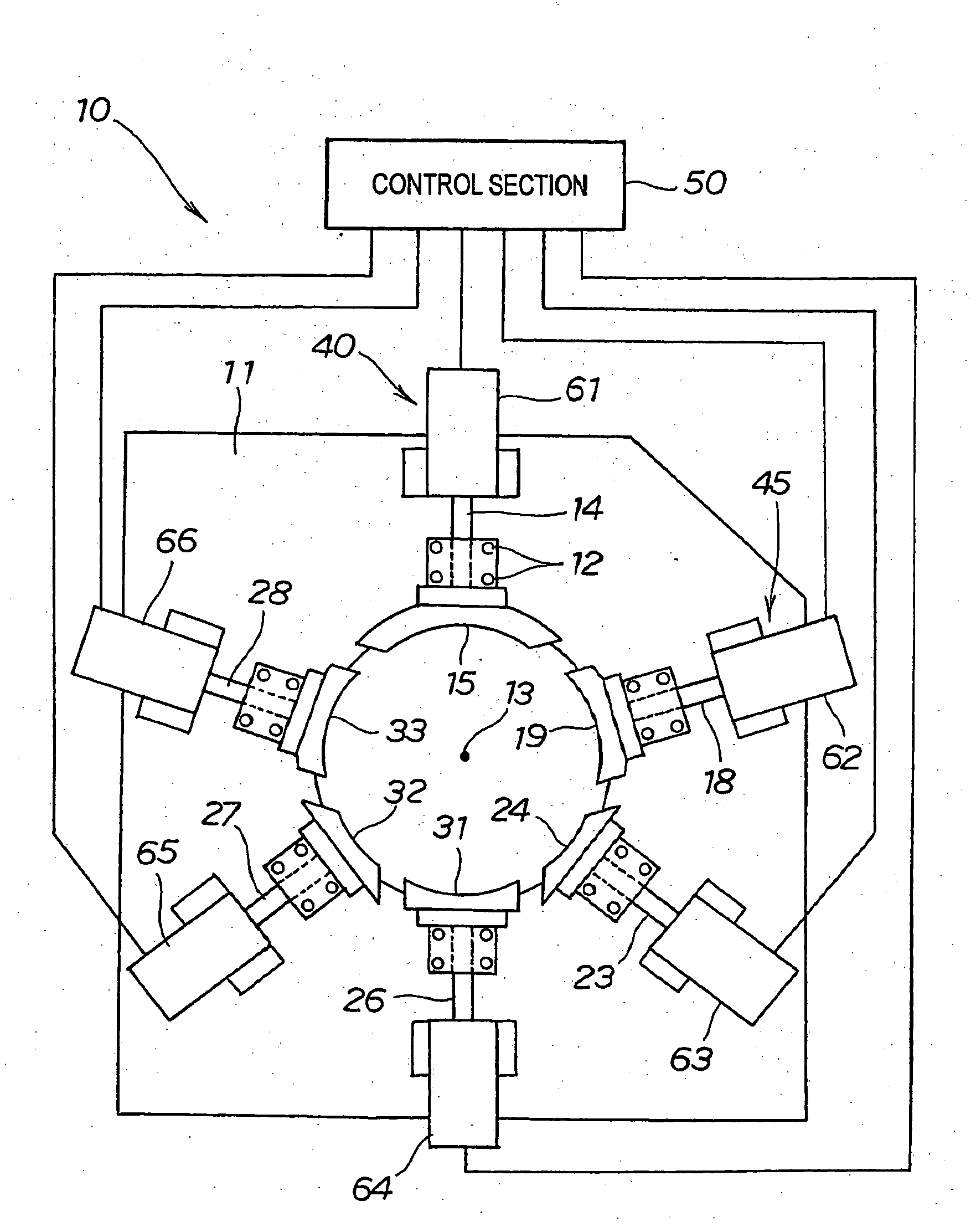
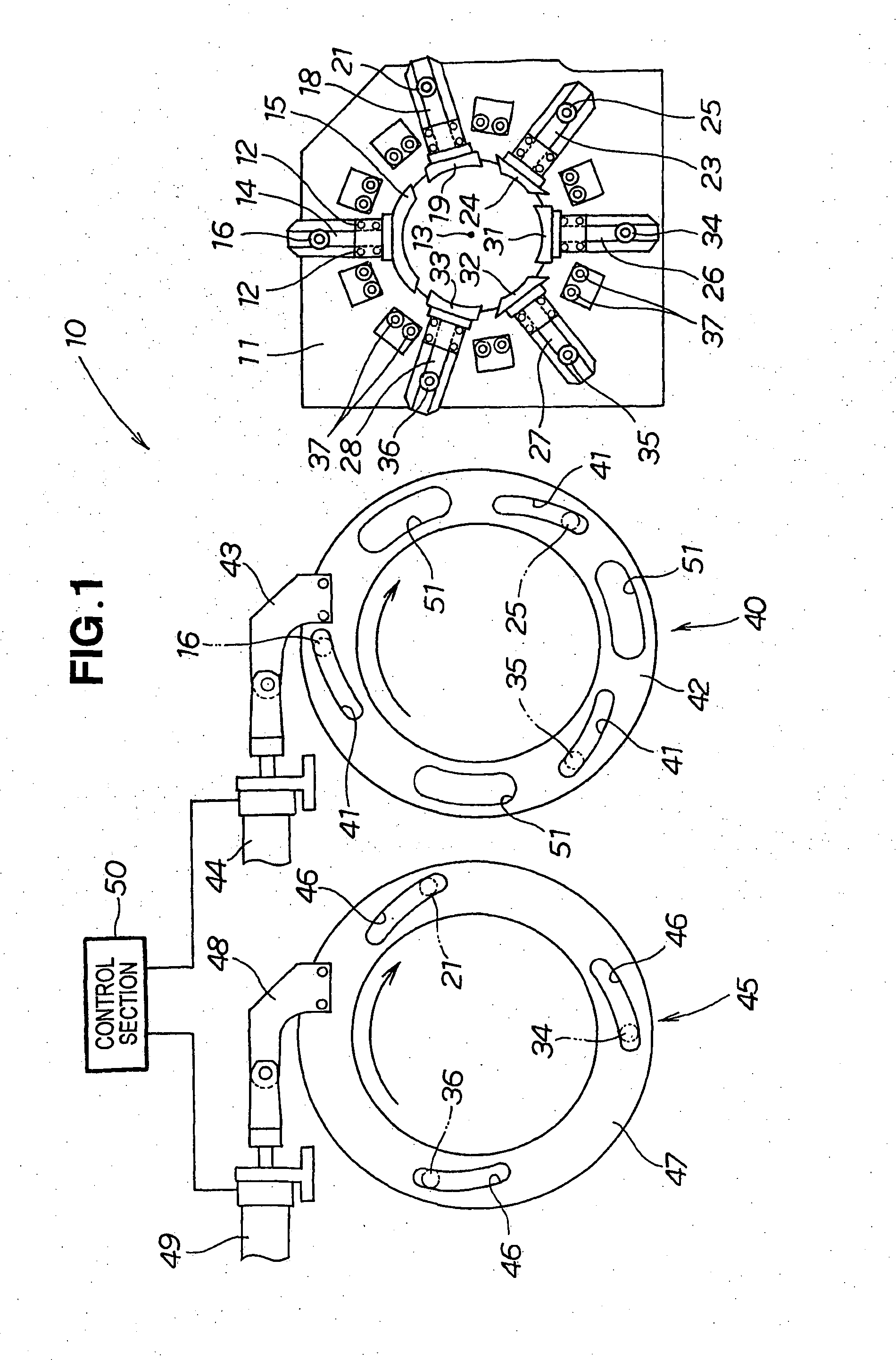
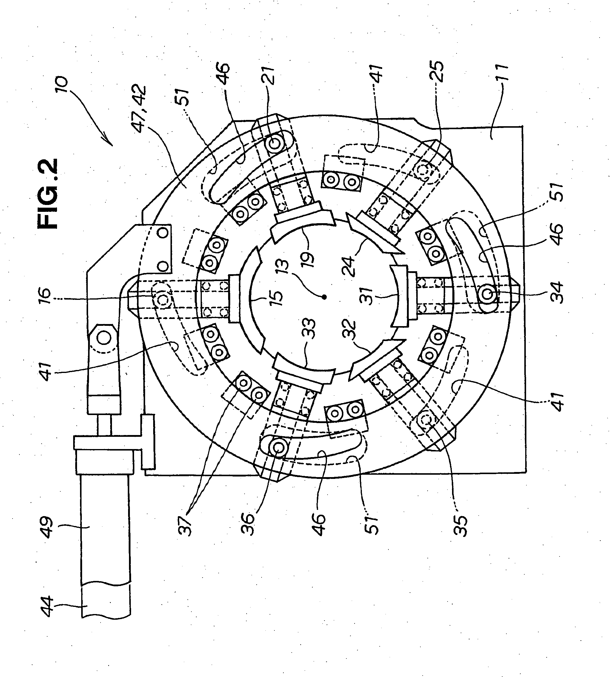
[0034]A mat compression apparatus 10 has a base 11, a first drive mechanism 40, and a second drive mechanism 45, as shown in FIG. 1.

[0035]The base 11 has a first rod 14 supported so as to be able to move toward a center point 13 by guides 12, 12 as supports for pressers, a first presser 15 disposed at a distal end of the first rod 14, and a first roller 16 disposed at a base part of the rod 14.

[0036]Furthermore, the base 11 has a second rod 18 supported so as to be able to move toward the center point 13 by the guides 12, 12; a second presser 19 disposed at a distal end of the second rod 18; and a second roller 21 disposed at a base part of the second rod 18. Furthermore, the base 11 has a third rod 23 supported so as to be able to move toward the center point 13 by the guides 12, 12; a third presser 24 disposed at a distal end of the third rod 23; and a third roller 25 disposed at a base part of the second rod 23.

[0037]In a similar manner, 26, 27, and 28 designate a fourth rod, a f...


PUM

PropertyMeasurementUnit
diameteraaaaaaaaaa
diameter d1aaaaaaaaaa
frictional forceaaaaaaaaaa

Abstract

A method for wrapping a mat (52) around a catalyst (57) used in an exhaust gas cleaning device and compressing the mat is disclosed. Odd-numbered first presser (15), third presser (24), and fifth presser (32) are caused to move forward in the manner of the arrow (3), and the mat is compressed. The mat is then completely compressed by causing even-numbered second presser (19), fourth presser (31), and sixth presser (33) to move forward.

Description

TECHNICAL FIELD[0001]The present invention relates to a technique for compressing a mat wrapped about a cylindrical catalyst.BACKGROUND ART[0002]Engine exhaust gas contains carbon monoxide, hydrocarbons, nitrogen oxide, and other undesirable substances. In view of this fact, an exhaust gas cleaning device is currently mounted in the exhaust systems of vehicle engines and the like. An exhaust gas cleaning device acts to remove or detoxify undesirable substances. A method for manufacturing an exhaust gas cleaning device will be described with reference to the drawings.[0003]A catalyst 201 having a circular cross-section is prepared, as shown in FIG. 11A hereof. A mat 202 is wrapped about the catalyst 201, as shown in FIG. 11B. At this point, the outside diameter of the mat 202 is D1.[0004]The mat 202 is then compressed until the outside diameter reaches d1, as shown in FIG. 11C and is inserted in a metal pipe 203 shown in FIG. 11D. An exhaust gas cleaning device 200 is obtained thereb...

Claims


Application Information

Patent Timeline
Patent Type & Authority Applications(United States)
IPC IPC(8): B21D51/16
CPCB23P11/005B23P2700/03Y10T29/49345F01N2450/00F01N3/2853
Inventor UMEDA, YOSHIHIRONAKAMURA, RYU
Owner YUTAKA GIKEN CO LTD
Why Eureka
Try Eureka