Electrical system and control method

a technology of electrical systems and control methods, applied in the field of electrical systems, can solve problems such as high cost, large filter components, and large size of switching actions

Active Publication Date: 2010-06-24
GENERAL ELECTRIC CO
View PDF3 Cites 45 Cited by
  • Summary
  • Abstract
  • Description
  • Claims
  • Application Information

AI Technical Summary

Benefits of technology

[0006]In accordance with an embodiment disclosed herein, a power generation system comprises at least two electrical systems connected in parallel at an electrical connection point. Each electrical system comprises a power conversion system comprising a converter including a plurality of switches for converting direct current power into alternating current power. The power generation system comprises a control system including at least two pulse width modulation (PWM) modulators, each PWM modulator for

Problems solved by technology

The switching actions tend to create undesirable harmonic

Method used


Image

  • Electrical system and control method
  • Electrical system and control method
  • Electrical system and control method

Examples


first embodiment

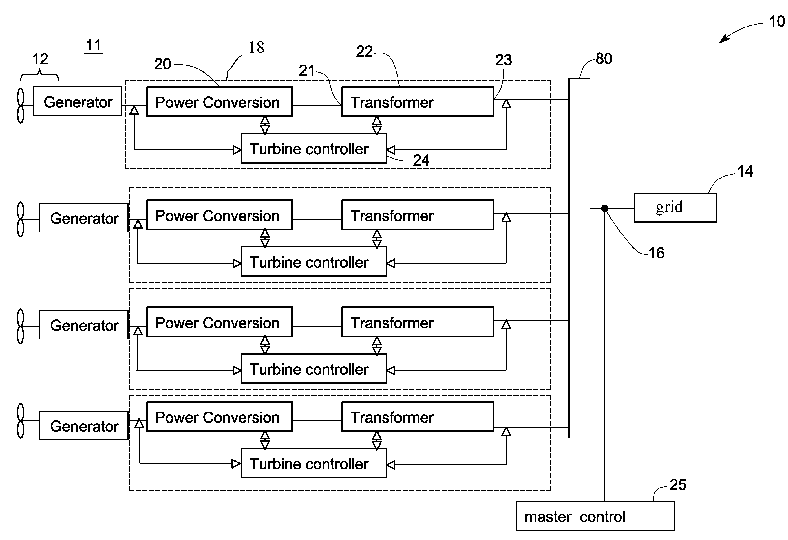
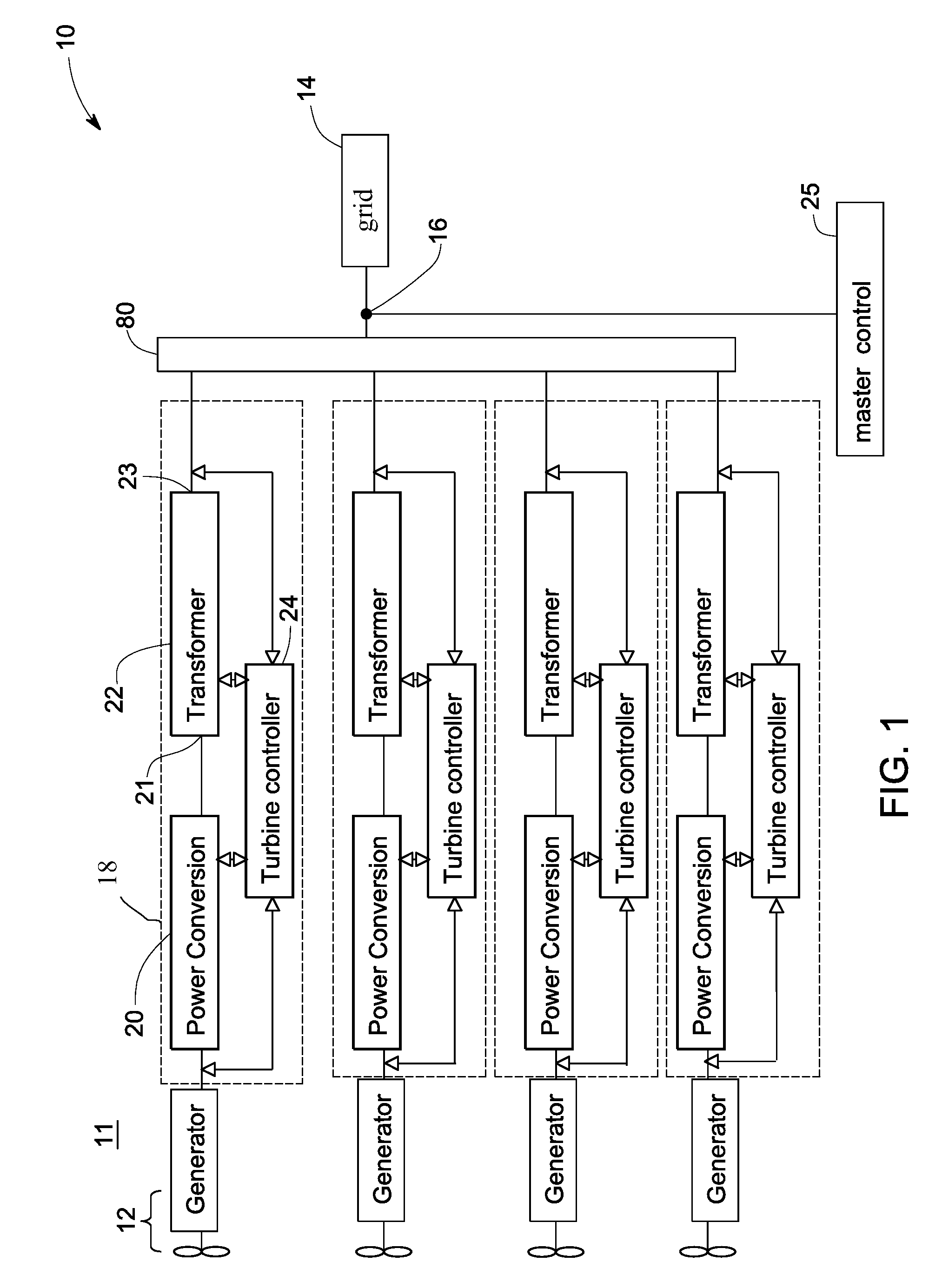
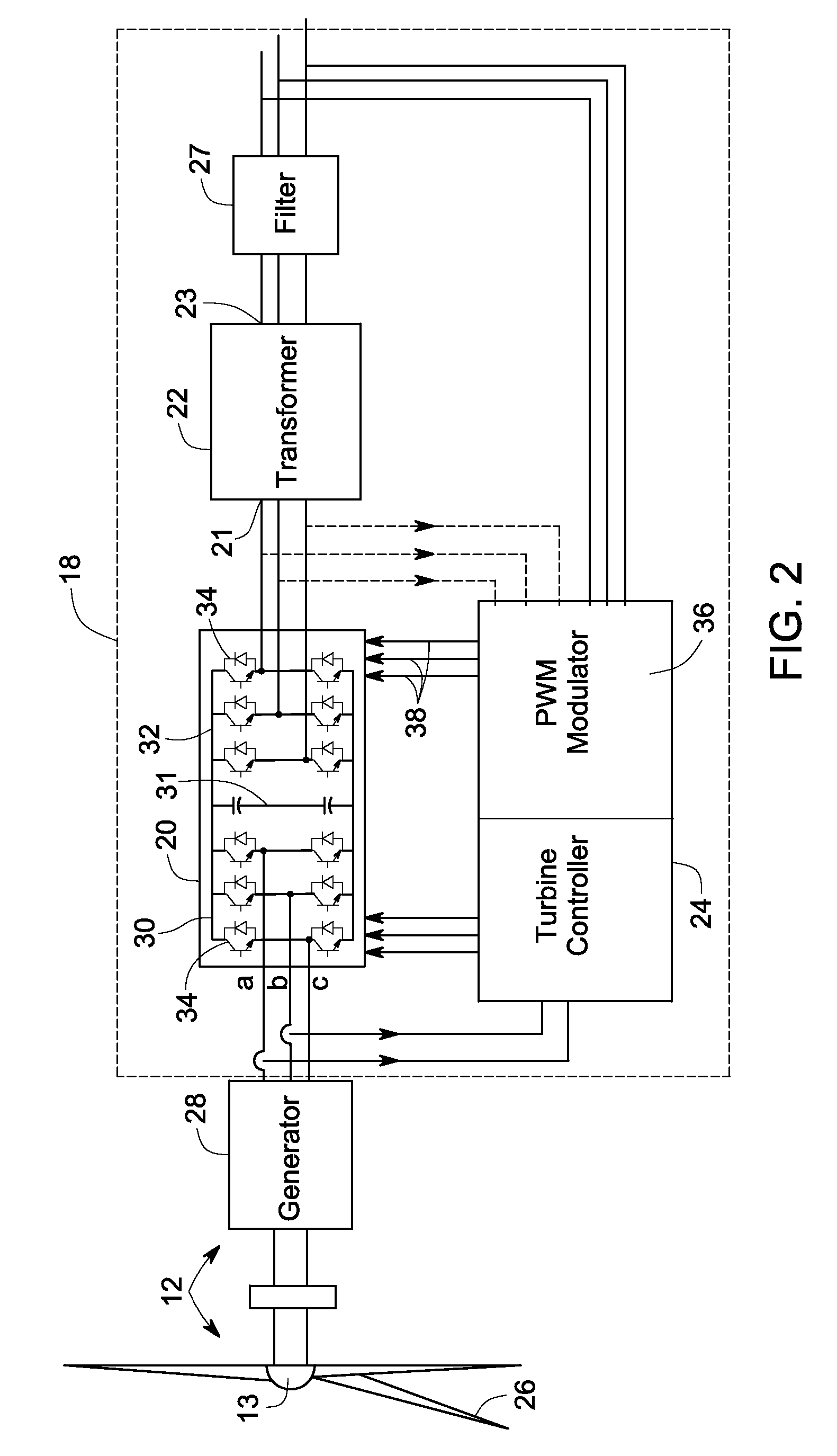
[0033]In the invention, PWM patterns for a corresponding phase, for example phase Ua, of different wind turbine electrical systems 18 are interleaved via master controller 25 and / or each wind turbine electrical system controller 24 (FIG. 2). In a more specific example, the carrier signals for individual wind turbine electrical systems 18 have the same frequency and amplitude, but are interleaved relative to each other over a carrier signal cycle. For example, each carrier signal may be spaced a degree of 360 / n with respect to the carrier cycle from the carrier signal of another wind turbine electrical system 18, wherein n is the number of wind turbine electrical systems 18 in power generation system 10. For a power generation system 10 with four wind turbine electrical systems 18, in one embodiment, each carrier signal of one phase of the grid side converter 32 is spaced from one another by 90 degrees.

[0034]Referring to FIG. 5, carrier signals 152, 252, 352 and 452 of four turbine s...

second embodiment

[0037]In the invention, referring back to FIGS. 1 and 2, PWM patterns for a corresponding phase, for example Ua, of grid side converter 32 in different wind turbine electrical systems 18 are phase shifted by a different technique wherein carrier signals for the corresponding phase of different wind turbine electrical systems 18 are the same, and the fundamental waveforms for the corresponding phase of different wind turbine electrical systems 18 are interleaved by being shifted between each other evenly over a fundamental waveform cycle by a degree of 60 / n, wherein n is the number of wind turbine electrical systems 18 in power generation system 10. The phase shifted PWM patterns drive the switches 34 and generate a plurality of voltage pulses. Turbine transformers 22 may be used to transform the voltage pulses and restore the shifted phases between wind turbine electrical systems 18.

[0038]In one specific embodiment, PLL circuits 40 of each wind turbine electrical system 18 are elect...

third embodiment

[0045]In another embodiment, PWM patterns of different wind turbine electrical systems 18 are both interleaved and phase shifted, and the turbine transformers restore shifted phases in the output waveforms. To some extent, the third embodiment is a combination of the embodiments described above with respect to FIGS. 5-6 and 7-9, and thus similar description is omitted hereinafter. As described above with reference to FIG. 8, by PWM shifting and transformer restoring between the four wind turbine electrical systems 18, only harmonic of orders N·6·t±1 remain, which may be further reduced by carrier signal interleaving.

[0046]In one specific embodiment, the carrier signal between the wind turbine electrical systems 18 are interleaved by t*60 / N degrees, wherein N is the number of wind turbine electrical systems 18 in power generation system 10 and t is an integer. For the exemplary power generation system 10 in FIG. 1 with four wind turbine electrical systems 18, the carrier signals betw...


PUM


Abstract

A power generation system comprises at least two electrical systems connected at an electrical connection point. Each electrical system comprises a power conversion system comprising a converter including a plurality of switches for converting direct current power into alternating current power. The power generation system comprises a control system including at least two pulse width modulation (PWM) modulators, each PWM modulator for obtaining a fundamental waveform and a carrier signal, using the fundamental and carrier signals to generate a PWM pattern, and for providing the PWM pattern to a respective converter for driving the switches of the respective converter. The control system is configured to interleave carrier signals, fundamental waveforms, or a combination of carrier signals and fundamental waveforms of the at least two electrical systems to generate interleaved PWM patterns respectively for the at least two converters.

Description

BACKGROUND[0001]The invention relates generally to electrical systems for providing electrical power to utility grids at interconnection points. More specifically, the invention relates to an electrical system which converts electrical power generated by renewable energy sources such as wind turbines and photovoltaic modules into electrical power which meets a low harmonic requirement of the interconnection point.[0002]Recently, renewable energy sources, such as wind turbines, have received increased attention as environmentally safe and relatively inexpensive alternative energy sources. With this growing interest, considerable efforts have been made to develop wind turbines that are reliable and efficient. To maximize the efficacy of power generation and to simplify connection to the utility grid, wind turbines are often located in proximity to one another, which are generally referred to in the pertinent arts as a “wind farm.” Wind turbines in the wind farm generate electrical pow...

Claims


Application Information

Patent Timeline
IPC IPC(8): H02M7/48
CPCH02J3/01Y02E40/40H02M7/53871H02J3/40
Inventor WANG, CHANGYONGTAN, ZHUOHUIDELMERICO, ROBERT WILLIAMRITTER, ALLEN MICHAELTEICHMANN, RALPHZHANG, RICHARD S.SEYMOUR, ROBERT ALLENYUAN, XIAOMING
Owner GENERAL ELECTRIC CO
Why Eureka
Try Eureka