Roller brushes for electrical machinery,

a technology of electrical machinery and roller brushes, applied in the direction of current collectors, dynamo-electric machines, electrical apparatus, etc., can solve the problems of arc-induced erosion, relatively poor electrical conductivity of graphite, and relatively short life span, so as to reduce radial stiffness

Inactive Publication Date: 2010-06-24
UNIV OF FLORIDA RES FOUNDATION INC
View PDF12 Cites 2 Cited by
  • Summary
  • Abstract
  • Description
  • Claims
  • Application Information

AI Technical Summary

Benefits of technology

[0008]In various other embodiments, a method of transferring electrical current to a rotor of a rotating electrical machine is provided. The method includes the steps of: (1) providing a stator and a rotor; (2) providing a plurality of roller elements that are adapted for transferring electrical current from the stator to the rotor; (3) compressing the plurality of roller elements; and (4) while the plurality of roller elements are compressed, inserting the plurality of roller elements intermediate the rotor and the stator. The roller elements have a reduced radial stiffness and are biased against a surface of the stator and a surface of the rotor. According to one embodiment, the step of compressing the roller elements includes the steps of (1) providing a plurality of substantially cylindrical bodies; and (2) compressing the substantially cylindrical bodies intermediate the stator and the rotor so that outward forces resulting from expansive properties of each particular substantially cylindrical body (A) urge the particular substantially cylindrical body into contact with the rotor and the stator; and (B) maintain the particular substantially cylindrical body in contact with the rotor and the stator.

Problems solved by technology

Brushes are often made from graphite, despite graphite's relatively poor electrical conductivity, and must be replaced at regular intervals as they wear out.
However, when current is passed through ball bearings or other roller elements, their life span may be greatly shortened as a result of arc-induced erosion.
Arc-induced erosion occurs when individual roller elements lose contact with the rotor or stator and small sparks or arcs occur.
Over time, the sparks cause damage to the surfaces of the roller elements, and this damage leads to premature failure of the roller elements.
However, due to manufacturing tolerances, roller elements cannot be manufactured this way.
In addition, because the individual roller elements typically have high stiffness, very large loads are required to bring the roller elements into contact simultaneously, and these large loads cause damage to the roller elements and shorten their life span.

Method used


Image

  • Roller brushes for electrical machinery,
  • Roller brushes for electrical machinery,
  • Roller brushes for electrical machinery,

Examples


Embodiment Construction

[0018]The present invention will now be described more fully hereinafter with reference to the accompanying drawings, in which various embodiments of the invention are shown. This invention may, however, be embodied in many different forms and should not be construed as limited to the embodiments set forth herein. Rather, these embodiments are provided so that this disclosure will be thorough and complete, and will fully convey the scope of the invention to those skilled in the art. Like numbers refer to like elements throughout.

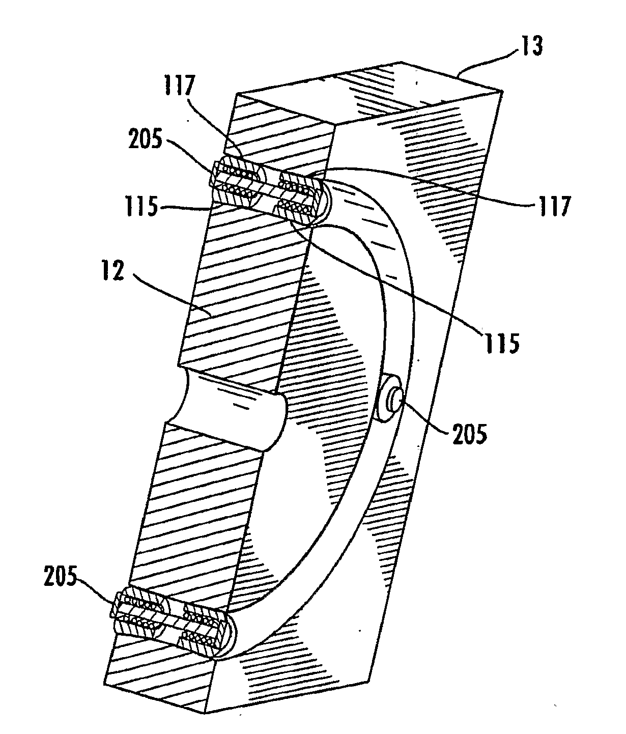
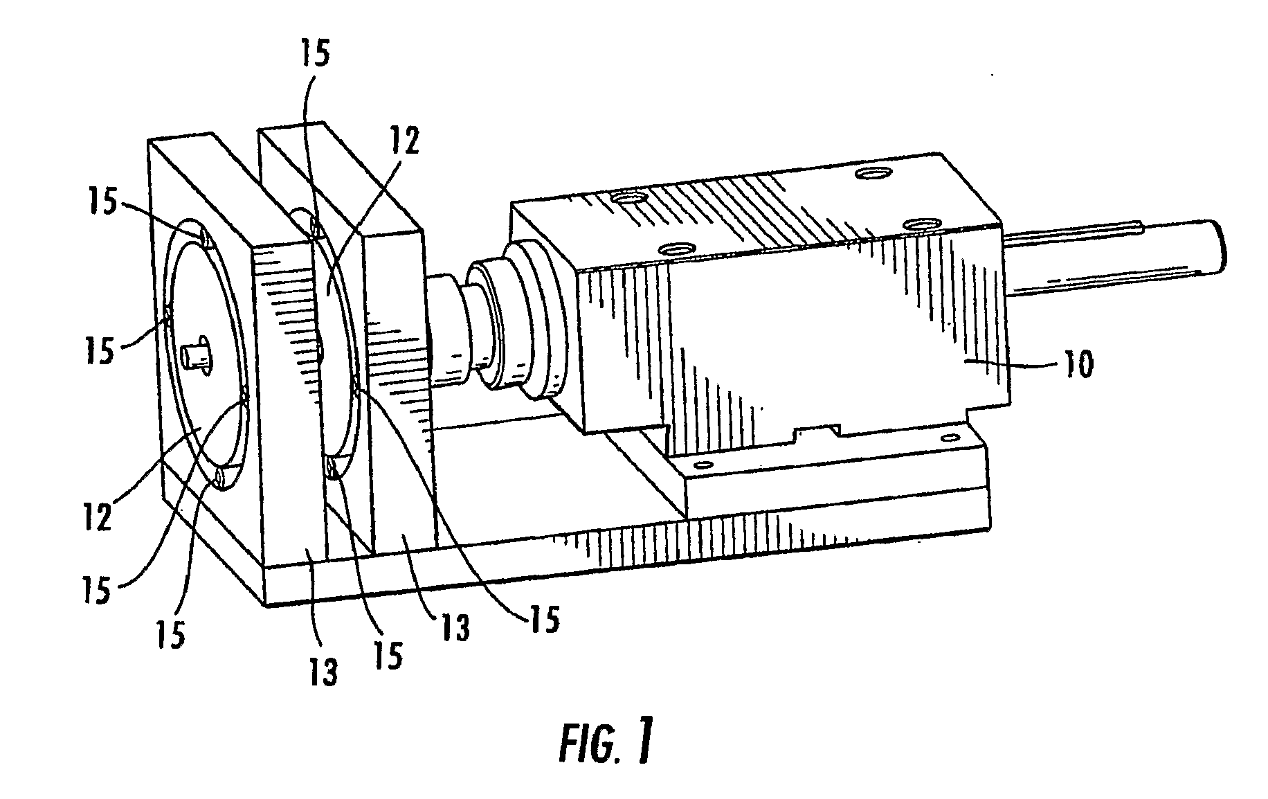
[0019]According to various embodiments of the invention, as shown in FIG. 1, a rotating electrical machine 10 (e.g., a motor or generator) is provided that includes at least one pair of a rotor 12 and a stator 13. The stator 13 receives electrical current from an electrical source and transfers the current to conductive roller elements 15 positioned between the rotor 12 and the stator 13. The conductive roller elements 15 transfer the current to the rotor 12...


PUM


Abstract

Various embodiments provide a rotating electrical machine (10) that includes an electrical supply coupled to a stator (13), a rotor (12), and a plurality of roller elements (or brushes) (15) for transferring electrical current from the stator (13) to the rotor (12). In one embodiment, each roller element (15) is compressed between the rotor (12) and the stator (13) so that outward forces resulting from expansive properties of each roller element (15) urge the roller element (15) into contact and maintain the roller element (15) in contact with the rotor (12) and the stator (13). For example, in one embodiment, each roller element (105) has a hollow, substantially cylindrical body formed of a conductive material that is elastically biased in a radially outward direction to maintain contact with the rotor (12) and the stator (13).

Description

BACKGROUND OF THE INVENTION[0001]Many types of rotating electrical machinery (e.g., motors and generators) require a means of transferring electrical current from an electrical supply to a rotor. In most cases, the operation of the machine is dependent on the existence of multiple poles on the rotor that must be energized in phase with the rotational position of the rotor. The energizing is normally accomplished through the use of “brushes” that slide on a surface of the rotor and sequentially contact individual poles. Brushes are often made from graphite, despite graphite's relatively poor electrical conductivity, and must be replaced at regular intervals as they wear out.[0002]Homopolar motors do not have multiple poles on the rotor. Therefore, the brushes are energized with the same voltage. As a result, sliding brushes are not necessary for transferring the current to the rotor. The current can also be transferred using conductive rollers, which are similar to ball or roller bea...

Claims


Application Information

Patent Timeline
Patent Type & Authority Applications(United States)
IPC IPC(8): H01R39/28
CPCH01R39/643H02K31/02H02K13/003
Inventor ZIEGERT, JOHN CHARLESSAWYER, WALLACE GREGORYDICKRELL, PAMELABARES, JASON
Owner UNIV OF FLORIDA RES FOUNDATION INC
Why Eureka
Try Eureka