Elastic wheel for rail traffic vehicle and assembling method and rigidity design method thereof

A rail transit vehicle and elastic wheel technology, which is applied in the direction of wheels, wheels, vehicle parts, etc. characterized by rail running parts, can solve the problem of poor radial lightening effect of the unsprung part of the vehicle, and improve structural stability and Reliability, reduced diameter-to-axis stiffness ratio, reduced maintenance cost and low effect

Active Publication Date: 2019-08-23
ZHUZHOU TIMES NEW MATERIALS TECH
View PDF12 Cites 2 Cited by
  • Summary
  • Abstract
  • Description
  • Claims
  • Application Information

AI Technical Summary

Problems solved by technology

[0012] For low-floor vehicles using motor direct drive in the prior art, since the radial stiffness of the elastic wheels is greater than the axial stiffness, the radial stiffness of the unsprung part of the vehicle The reduction effect is not good. In order to ensure the safety performance of the motor, prolong the service life, and improve the ride comfort, it is necessary to improve the vibration of the unsprung part of the vehicle to ensure that the low-floor vehicle achieves the best vibration and noise reduction effect

Method used


Image

  • Elastic wheel for rail traffic vehicle and assembling method and rigidity design method thereof
  • Elastic wheel for rail traffic vehicle and assembling method and rigidity design method thereof
  • Elastic wheel for rail traffic vehicle and assembling method and rigidity design method thereof

Examples


Embodiment 1

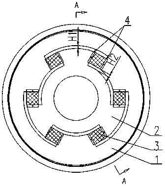
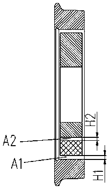
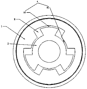
[0041]An elastic wheel for a rail transit vehicle, comprising a tire 1, a wheel core 2 concentrically arranged in the tire 1, and a rectangular parallelepiped elastic body 3 detachably connected between the tire 1 and the wheel core 2, characterized in that The tire 1 and the wheel core 2 are spaced radially to form a radial gap A, and separated along the circumferential direction to form a circumferential gap B, and the circumferential gap B is evenly distributed along the circumferential direction N×2 and N≥3, each An elastic body 3 is compressed in each of the circumferential gaps B, and the elastic body 3 is separated from the tire 1 and the wheel core 2 in the radial direction without contact.

[0042] As shown in the figure, the elastic body 3 is compressed in the circumferential gap B in the circumferential direction, and is separated from the tire 1 and the wheel core 2 in the radial direction without contact. When the elastic wheel is subjected to a vertical force, the...

Embodiment 2

[0047] The difference from Embodiment 1 is that the elastic body 3 is a metal rubber pad composed of multi-layer metal plates and rubber vulcanized between the metal plates, and the metal plates at the end of the elastic body 3 are arranged in parallel with the tire 1 or the wheel core 2 are detachably connected. Such as Figure 6 As shown, the elastic body is composed of a metal plate and rubber vulcanized between the metal plates. The stiffness of the elastic body is increased by adding the metal plate, so that the thickness of the metal plate and rubber in the elastic body 3 can be adjusted according to the rigidity requirements of the elastic wheel. The ratio and the structure of the metal plate adjust the radial stiffness and axial stiffness of the elastic body, thereby adjusting the radial stiffness, axial stiffness and diameter-axis stiffness ratio of the elastic wheel, so that the radial-axis stiffness of the elastic wheel is equal to 1 or greater than 1, To meet the ...

Embodiment 3

[0049] The difference from Embodiment 1 is that the elastic body 3 includes two end plates 31 , multiple outer partitions 32 and a middle plate 33 , and the partitions 32 and the middle plate 33 are arranged between the two end plates 31 The separators 32 are symmetrically arranged on both sides of the middle plate 33, the end plates 31 and the separators 32, the adjacent separators 32, and the middle plate 33 and the separators 32 are bonded by rubber vulcanization, and the bonding of the middle plate 33 The surface is two mirror-symmetrical V-shaped surfaces 33.1, the separator 32 is a V-shaped plate parallel to the V-shaped surface 33.1, the bonding surface of the end plate 31 is V-shaped parallel to the V-shaped surface 33.1, and the V-shaped surface 33.1 The V-shaped angle β is 0~60 degrees. Such as Figure 7 As shown, the bonding surface of the middle plate 33 is V-shaped. After the elastic body 3 is compressed in the circumferential gap B, the radial thickness of the m...


PUM


Abstract

An elastic wheel for a rail traffic vehicle comprises a tire, a wheel core and elastic bodies, wherein the tire and the wheel core are radially separated to form radial clearances and are circumferentially separated to form circumferential clearances; N*2 circumferential clearances are circumferentially uniformly distributed, and N is not less than 3; each elastic body is compressed into the corresponding circumferential clearance; the elastic bodies are radially separated from the tire and the wheel core without contact; and the circumferential clearances are arranged parallel to two sides towhich the elastic bodies are clung. With the adoption of the elastic wheel for the rail traffic vehicle, the radial rigidity of the elastic wheel can be effectively reduced; the radial axis rigidityratio of the elastic wheel is reduced; the vibration condition of a lower part of a vehicle spring is reduced; the structure stability and reliability of the elastic wheel is improved; the rigidity demand of the lower part of the vehicle spring in a low-floor vehicle under different route conditions can be met; the use safety of the elastic wheel is improved; the production cost and the maintenance cost of the elastic wheel are low; and the practicability of the elastic wheel is improved. The invention also supplies an assembling method and a rigidity design method of the elastic wheel for therail traffic vehicle.

Description

technical field [0001] The invention relates to an elastic wheel for rail vehicles, an assembly method and a stiffness design method thereof, and belongs to the technical field of elastic wheels for rail vehicles. Background technique [0002] The elastic wheel is an elastic element embedded in a compressed state between metal parts, which can effectively reduce the vibration and noise when the vehicle is running. By adjusting the compression state of the elastic body, the stiffness of the elastic wheel can be changed and the performance of the wheel can be adjusted. [0003] The shear type elastic wheel rubber part of the traditional structure is perpendicular to the wheel axis, and the radial stiffness and axial stiffness are adjusted to form a shear force between the metal part and the rubber part. Since the rigidity of the rubber parts will decrease after long-term compression and deformation, the rubber parts will slip in the inner cavity of the wheel. [0004] The bol...

Claims


Application Information

Patent Timeline
Patent Type & Authority Applications(China)
IPC IPC(8): B60B17/00
CPCB60B17/0027
Inventor 颜瑶胡伟辉肖祥龙刘文松雷军玉贺小龙庄征宇曾慧
Owner ZHUZHOU TIMES NEW MATERIALS TECH
Why Eureka
Try Eureka