Electromechanical actuating drive

a technology of electric motor and drive shaft, applied in piezoelectric/electrostrictive/magnetostrictive devices, piezoelectric/electrostriction/magnetostriction machines, electrical apparatus, etc., can solve the problems of high material cost, coils and permanent magnets are the most expensive items, and the cost of components is high, so as to achieve low energy requirements, high reliability, and small design format

Inactive Publication Date: 2010-06-24
SIEMENS AG
View PDF8 Cites 2 Cited by
  • Summary
  • Abstract
  • Description
  • Claims
  • Application Information

AI Technical Summary

Benefits of technology

[0008]The electromechanical actuating drive or rotatory actuating drive is operated with the aid of solid-state actuators, in particular strip-shaped solid-state bending actuators, as electromechanical energy converter elements. Bending actuators of this type based on piezoelectric ceramic material, which are referred to in the present context as electromechanical drive elements, have been used in different designs in multifarious applications in industry for many years. They are characterized by a small design format, low energy requirements and high reliability. Thus, for example, a piezoelectric bending actuator exhibits a service life of at least 109 cycles in the industrial environment.
[0009]The at least two electromechanical, preferably piezoelectric, drive elements are arranged in such a way that their directions of movement are decoupled from each other, with the result that the drive elements do not obstruct each other in their movement or impede each other only to a negligibly small degree. For that purpose the drive elements are secured at least at one end with the aid of a sliding gate or a shear-soft, pressure- and tension-stable flexible structure. The sliding gate or, as the case may be, shear-soft, pressure- and tension-stable flexible structure allows free or approximately free movement of the drive elements in their longitudinal direction relative to the drive ring, while in another direction, preferably perpendicular to the longitudinal axis of the drive element, they are rigidly or immovably fixed. In this way the electrical energy converted into motion by the drive elements is optimally transferred onto the drive ring without energy losses occurring due to the mutual obstruction of the drive elements.

Problems solved by technology

In terms of component costs, the coils and the permanent magnet are the most expensive items.
Also critical for the price in addition to the material costs are the manufacturing costs, which increase approximately proportionally to the number of components making up the actuating drive.
These high material costs as well as the increase in manufacturing overhead for the actuating drive as the number of individual parts grows have a disadvantageous impact in terms of its mass production.

Method used


Image

  • Electromechanical actuating drive
  • Electromechanical actuating drive
  • Electromechanical actuating drive

Examples


Embodiment Construction

[0025]Reference will now be made in detail to the preferred embodiments of the present invention, examples of which are illustrated in the accompanying drawings, wherein like reference numerals refer to like elements throughout.

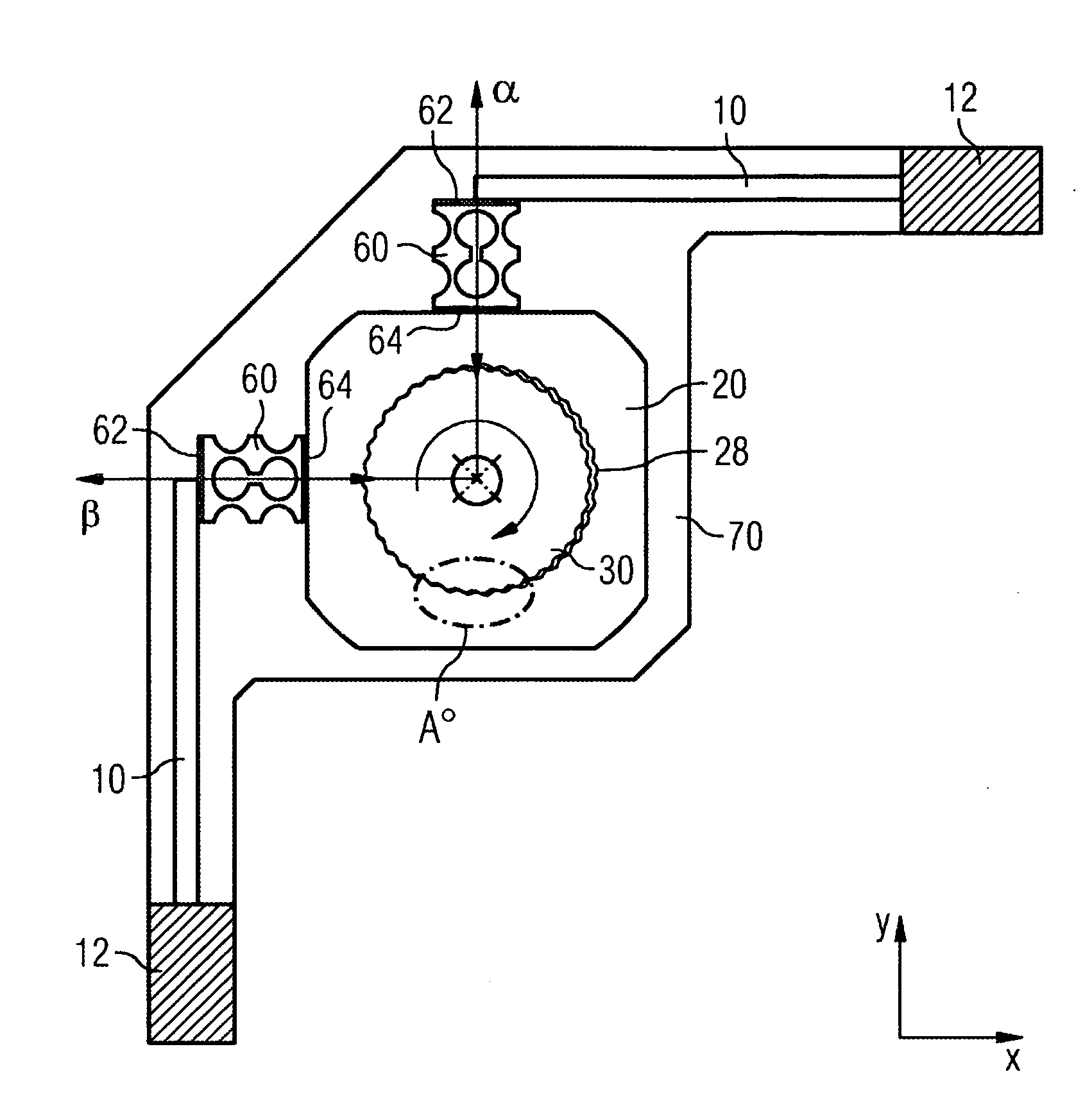
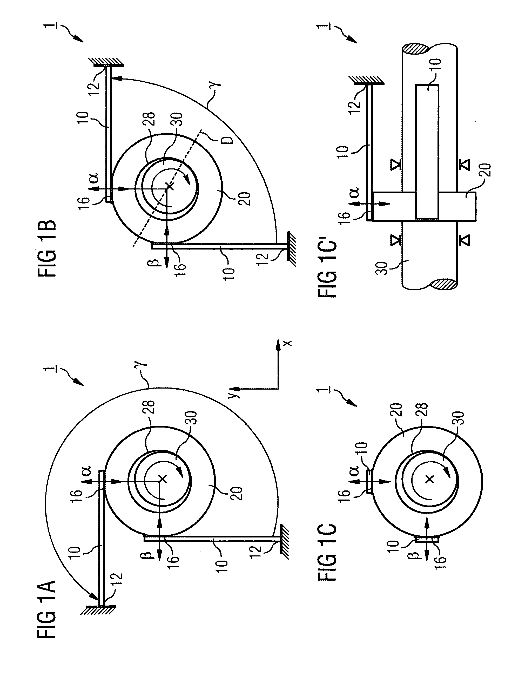
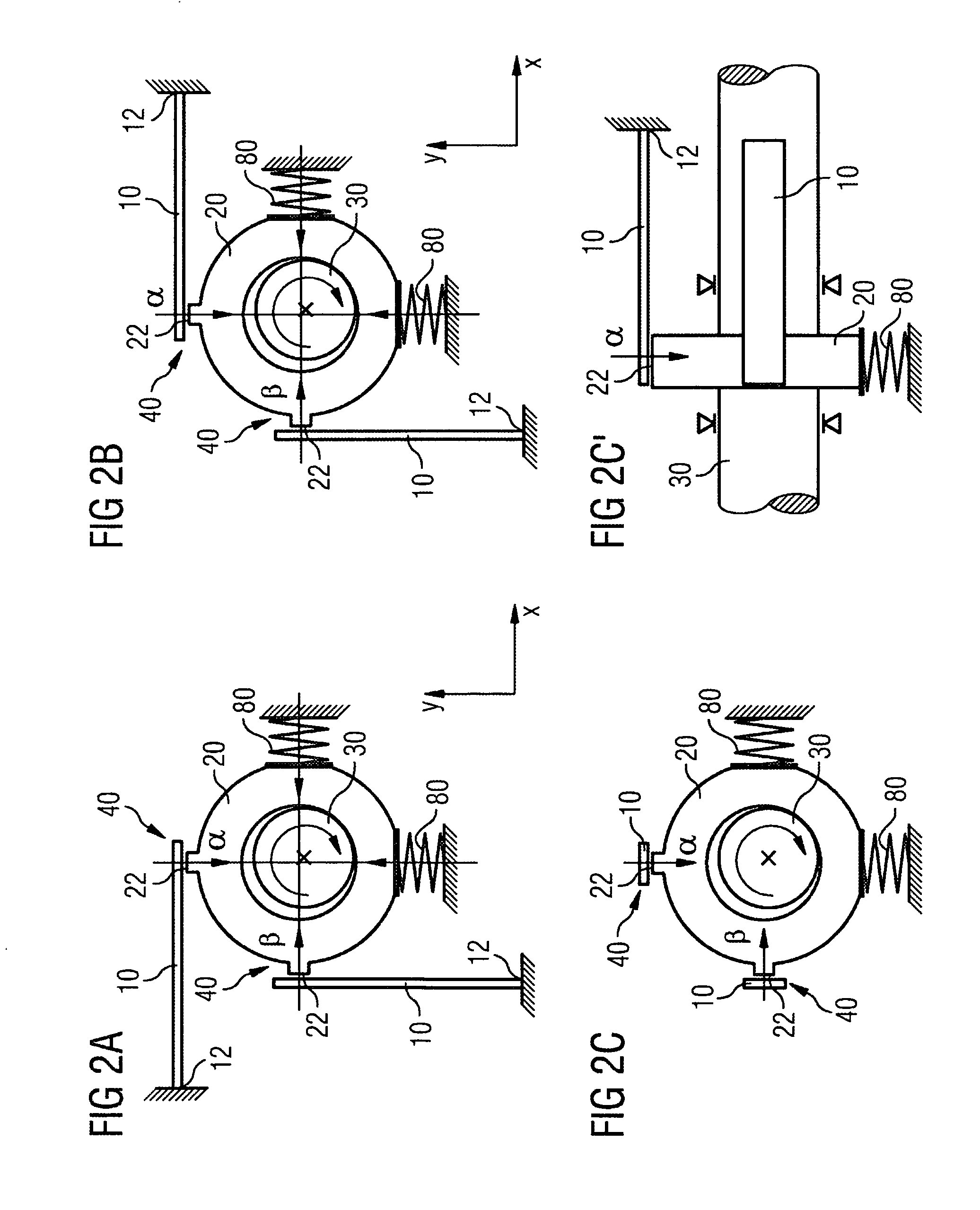
[0026]A piezoelectric stepper motor 1 is presented which permits a continuous and uniform rotation to be generated by an overlaying of suitable periodic linear movements of the bending transducers 10. For that purpose the bending transducers 10 are coupled to a flat drive ring 20 in such a way that the latter can be translated in an effective plane along the effective directions α, β of the bending transducers 10. The bending transducers 10 are preferably arranged such that their effective lines or, as the case may be, effective directions α, β intersect at an angle of approximately 90°. The drive ring 20 contains a cylindrical bore 28 having a specific diameter. The bore axis runs ideally vertically with respect to the effective plane which is spanned by the...


PUM


Abstract

An electromechanical actuating drive, in particular a piezoelectric microstepper motor, has two piezoelectric bending transducers having in each case an effective direction not oriented parallel to one another. Said bending transducers act on a drive ring in order, via the latter, to rotate a shaft. The bending transducers are articulated via a sliding coupling or a shear-flexible structure, thereby minimizing mutual obstruction of the bending transducers during the displacement movement.

Description

CROSS REFERENCE TO RELATED APPLICATIONS[0001]This application is based on and hereby claims priority to PCT Application No. PCT / EP2007 / 055357 filed on May 31, 2007 and German Application No. 10 2006 044 000.5 filed on Sep. 19, 2006, the contents of which are hereby incorporated by reference.BACKGROUND OF THE INVENTION[0002]The present invention relates to an electromechanical actuating drive, in particular a piezoelectric stepper motor.[0003]The central instrument console of a motor vehicle attempts to realize an optimal interplay between design and technology. Various pointer instruments are situated therein in the driver's field of view. The pointer instruments must not only satisfy different technical requirements but must also be priced competitively in order to be suitable for use in the mass production of motor vehicles. An example of a pointer instrument of said type is the “Messwerk 2000” system from the company Siemens VDO.[0004]The “Messwerk 2000” product is based on a ste...

Claims


Application Information

Patent Timeline
Patent Type & Authority Applications(United States)
IPC IPC(8): H01L41/09
CPCH02N2/105
Inventor BLUME, HEINRICH-JOCHENGOTTLEB, BERNHARD
Owner SIEMENS AG
Why Eureka
Try Eureka