Input device and data processing system

a technology of input device and data processing system, which is applied in the direction of electric digital data processing, instruments, computing, etc., can solve the problems of inability for users to hold the device in a manner, adversely affect the operating properties of the input device, detection errors, etc., and achieve enhanced convenience of three-dimensional input device, excellent operating properties, and high convenience

Inactive Publication Date: 2010-06-24
SEIKO EPSON CORP
View PDF12 Cites 21 Cited by
  • Summary
  • Abstract
  • Description
  • Claims
  • Application Information

AI Technical Summary

Benefits of technology

[0045]Through the use of at least one of the aspects of the present invention described above, the convenience of a three-dimensional input device is enhanced. The use of three-dimensional space is becoming increasingly common in three-dimensional CAD, games, and the like on computers, and there is thus an increasing need for a highly convenient system that utilizes a three-dimensional input device capable of inputting three-dimensional movement. Through the present aspect, a data processing system can be provided that utilizes a small-sized three-dimensional input device having excellent operating properties.

Problems solved by technology

Specifically, a detection error occurs due to rotation of the main body (housing) about the axis (X-axis) other than the detection axes (Y-axis, Z-axis).
In this case, the operating properties of the input device are adversely affected.
Particularly when a button, touch sensor, or the like that is necessary for operation is provided to the main body of the input device, the limitation described above makes it impossible for the user to hold the device in a manner that enables easy operation, and the user is forced to hold the device in an inconvenient manner.
This drawback places a burden on the user.
As the user holds and operates the main body of the input device, some unwanted and unintentional rotation of the main body is unavoidable during actual use.
However, in this case, the data processing device must compute a displacement amount for a control object (e.g., cursor pointer) in a display unit based on the received angular velocity signal, and the load on the data processing device is correspondingly increased.

Method used


Image

  • Input device and data processing system
  • Input device and data processing system
  • Input device and data processing system

Examples


first embodiment

Example of Use of Three-Dimensional Input Device

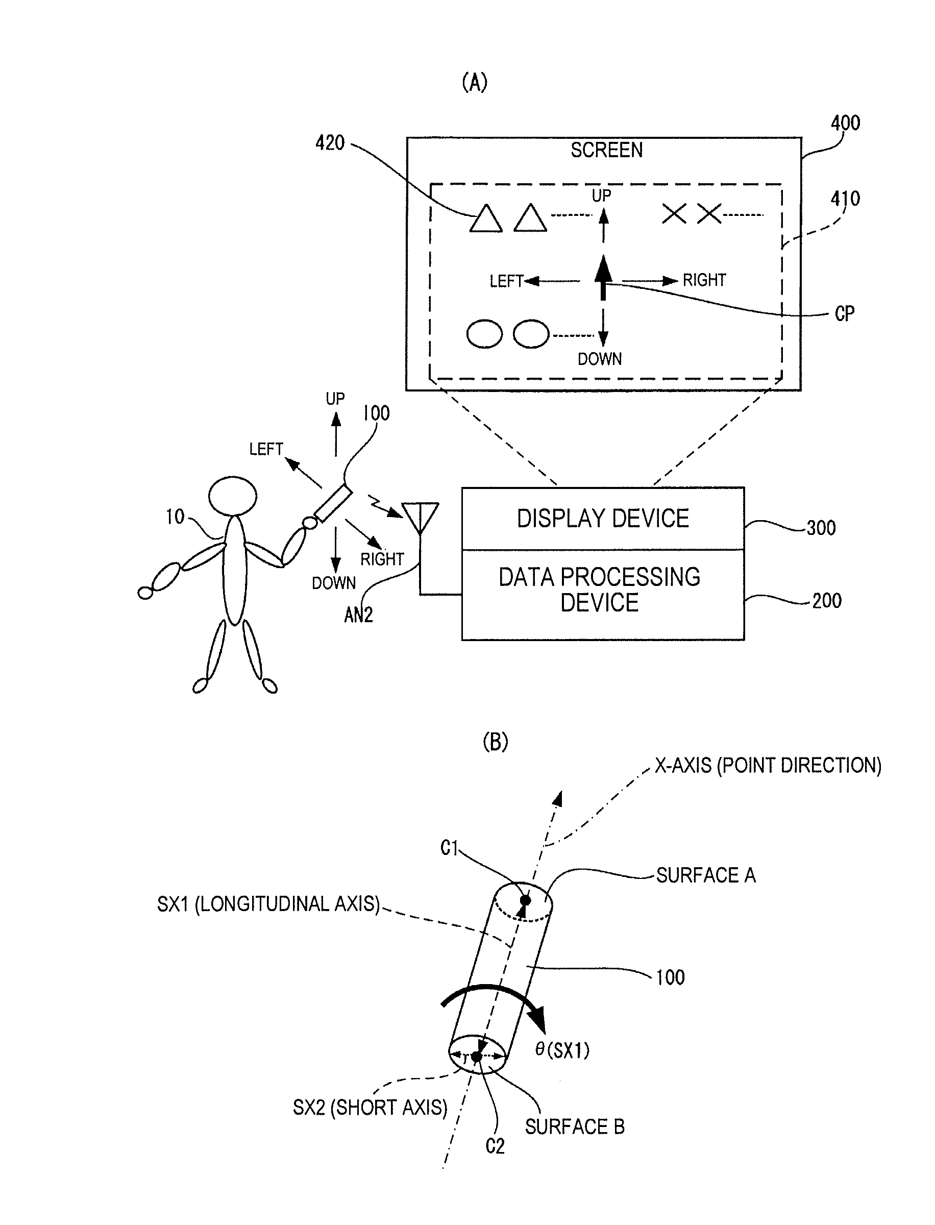
[0058]FIGS. 1(A) and 1(B) are views showing an example of the configuration of a data processing system that utilizes an input device (in this instance, a three-dimensional input device is a pointing device that can be used instead of a laser pointer, for example). As shown in FIG. 1(A), a user 10 holds an input device 100 in his right hand, and the distal end part of the main body (housing) of the input device 100 points to a cursor pointer (sometimes referred to hereinafter simply as a pointer) CP displayed on a screen 400. In the following description, the direction in which the main body (housing) of the input device 100 points is referred to as the “pointing direction” or the “point direction.” The point direction (pointing direction) is the “direction in which the distal end of the main body (housing) of the input device 100 points in space,” and the point direction (pointing direction) coincides with the X-axis direction as defi...

second embodiment

[0106]FIG. 10 is a view showing the configuration of another example of the input device. In the input device 100 shown in FIG. 10, the operating unit (output enable switch) 700 and an input interface 702 are added to the configuration shown in FIG. 8. The operating unit (output enable switch) 700 functions as a mode switch for switching between enabling / disabling (enable / disable) signal output from the input device 100.

[0107]In the present embodiment, an enable signal EN is at an active level, and a signal is outputted from the input device 100 only when the operating unit 700 is being operated (e.g., only when the output enable switch is being pressed). Consequently, during periods in which the operating unit 700 is not being operated (e.g., periods in which the output enable switch is not pressed), even when the user moves the main body (housing) of the input device 100, there is no change in the position of the control object (e.g., cursor pointer CP) in the display unit 660 of ...


PUM


Abstract

An input device includes a main body, a motion sensor unit and a coordinate conversion processing unit. The coordinate conversion processing unit configured to perform coordinate conversion processing based on a Y-axis acceleration and a Z-axis acceleration detected by the motion sensor unit with a first two-dimensional orthogonal coordinate system being defined by a mutually orthogonal Y-axis and Z-axis in a first plane perpendicular to an X-axis coinciding with a pointing direction of the main body. The coordinate conversion processing unit is configured to convert the Y-axis angular velocity and the Z-axis angular velocity detected by the motion sensor unit to a U-axis angular velocity and a V-axis angular velocity, respectively, in a second two-dimensional orthogonal coordinate system defined by a U-axis corresponding to a horizontal axis in the first plane and a V-axis perpendicular to the U-axis in the first plane.

Description

CROSS-REFERENCE TO RELATED APPLICATIONS[0001]This application claims priority to Japanese Patent Application No. 2008-321908 filed on Dec. 18, 2008. The entire disclosure of Japanese Patent Application No. 2008-321908 is hereby incorporated herein by reference.BACKGROUND[0002]1. Technical Field[0003]The present invention relates to an input device and to a data processing system and the like.[0004]2. Related Art[0005]The need has recently increased for a system that utilizes an input device for generating and outputting a physical quantity signal in accordance with the movement (including at least one of the orientation (including rotation) of a main body and the movement (including translational movement) of a main body) of a main body (housing) in space (e.g., a three-dimensional mouse or the like).[0006]Japanese Laid-Open Patent Publication No. 2001-56743, for example, discloses a technique that utilizes a button-operated device in which a cursor pointer is moved on an image disp...

Claims


Application Information

Patent Timeline
Patent Type & Authority Applications(United States)
IPC IPC(8): G06F3/033G06F3/038
CPCG06F3/0383G06F3/0346
Inventor NAKAOKA, YASUSHI
Owner SEIKO EPSON CORP
Why Eureka
Try Eureka