
Adaptive mapping for heterogeneous processing systems

a processing system and heterogeneous technology, applied in the field of adaptive mapping for heterogeneous processing systems, can solve the problems of requiring significant effort to map a given computation to the underlying hardware, requiring extra and often tedious programming effort, and difficult to program these machines

Inactive Publication Date: 2010-06-24
INTEL CORP
View PDF15 Cites 50 Cited by
  • Summary
  • Abstract
  • Description
  • Claims
  • Application Information

AI Technical Summary

Problems solved by technology

While these machines provide large computation bandwidth, the job of programming these machines can be very challenging for two reasons.
As a result, extra and often tedious programming effort is required to coordinate the control and data flows between the host and the additional element, just to ensure correctness.
Second, significant effort is required to map a given computation to the underlying hardware in order to achieve performance goals.
This is particularly challenging if a given computation can run on either / both the host processor and the additional element.
This approach may be unduly burdensome for all but the most expert programmers.
Furthermore, this static mapping approach is not only labor intensive but also fails to provide the flexibility to adapt the mapping based on changes in runtime environments.

Method used


Image

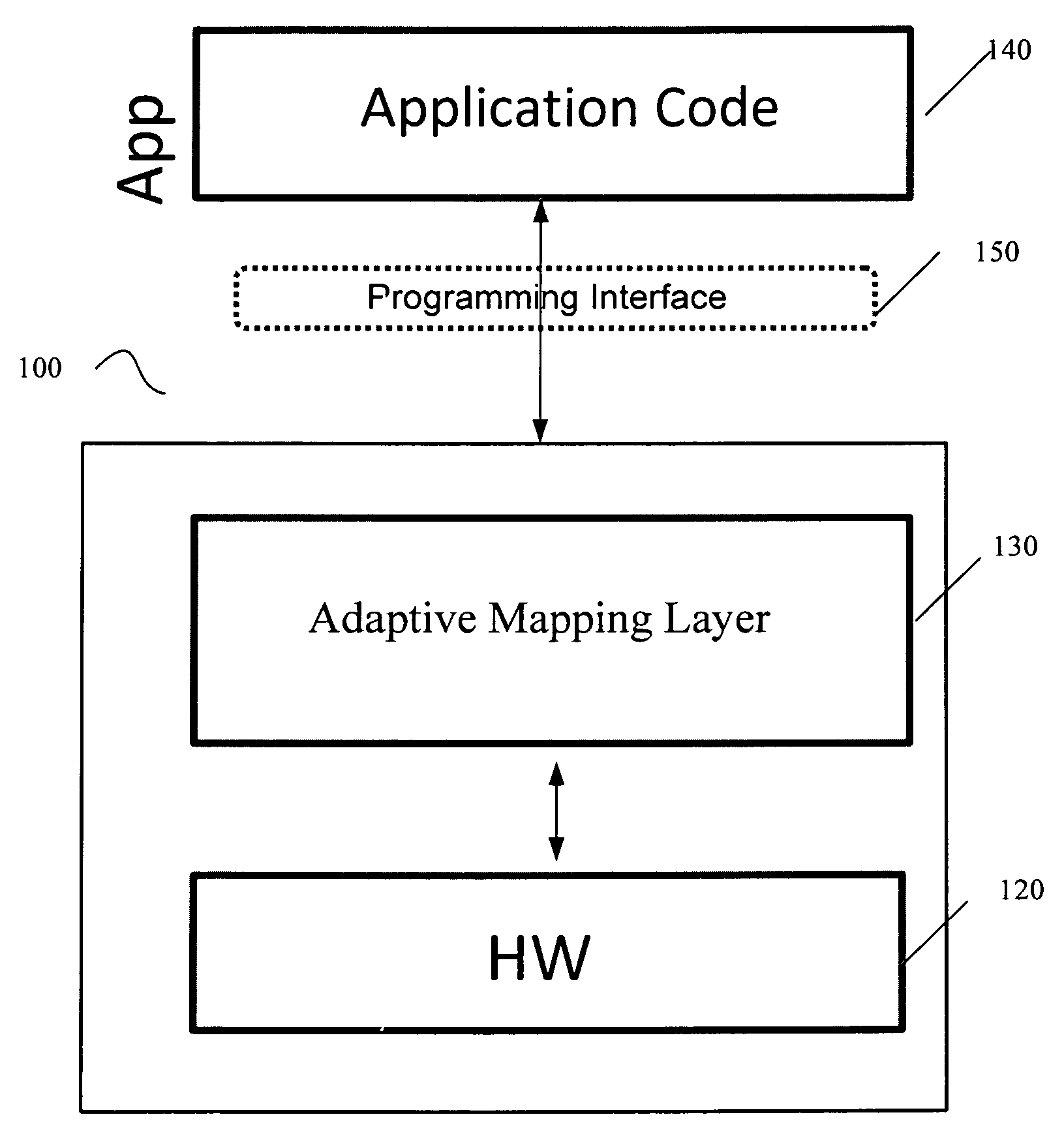
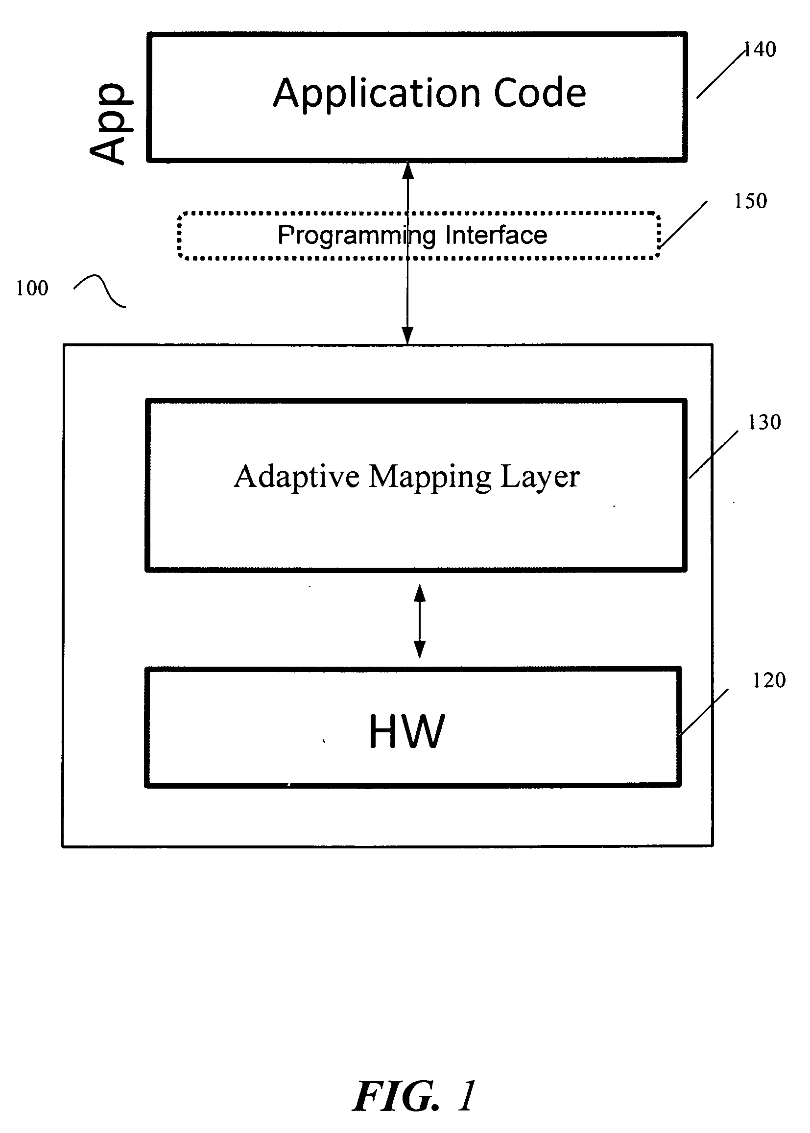
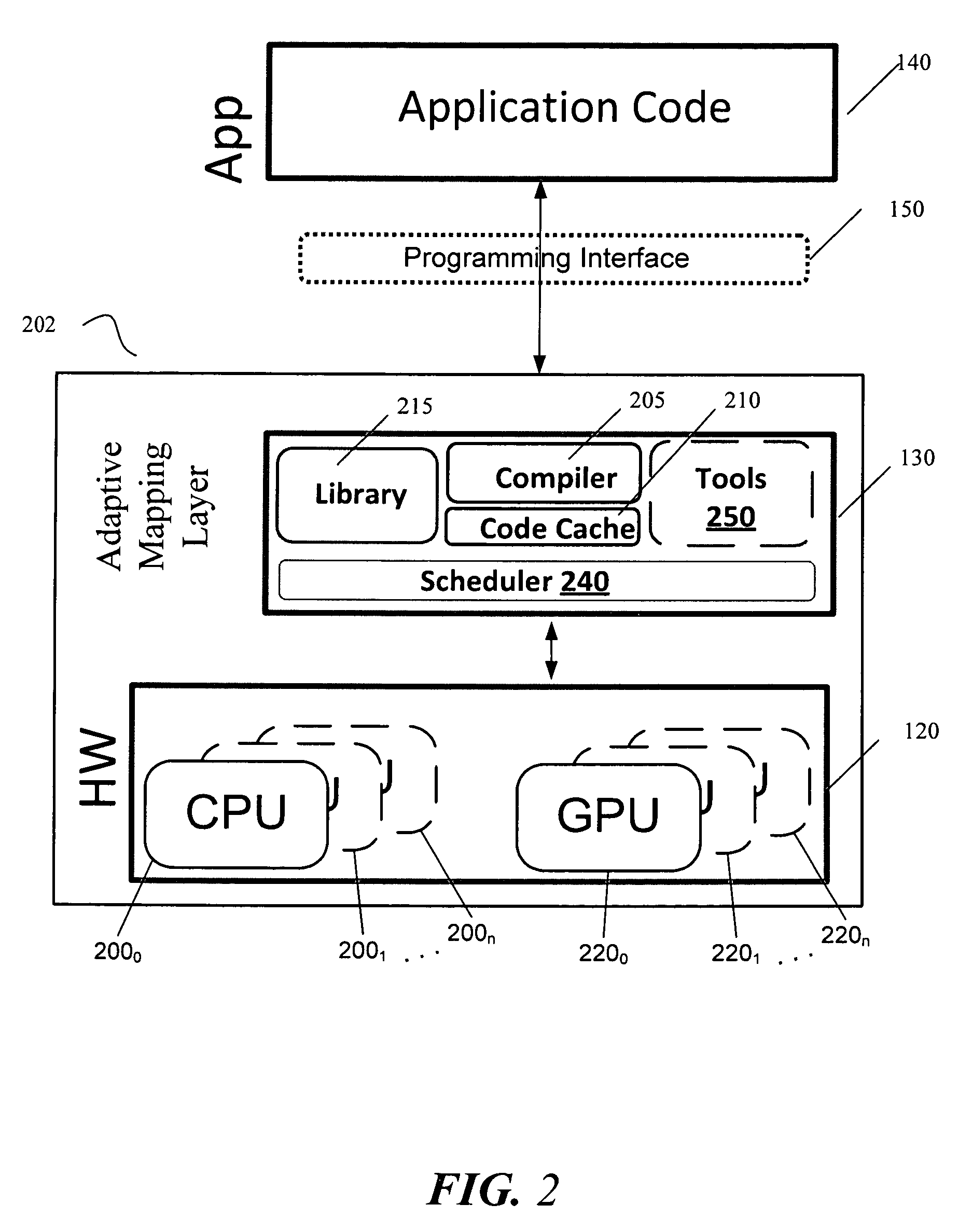
  • Adaptive mapping for heterogeneous processing systems
  • Adaptive mapping for heterogeneous processing systems
  • Adaptive mapping for heterogeneous processing systems

Examples


embodiment 600

[0082]Referring now to FIG. 6, shown is a block diagram of a second system embodiment 600 in accordance with an embodiment of the present invention. As shown in FIG. 6, multiprocessor system 600 is a point-to-point interconnect system, and includes a first processing element 670 and a second heterogeneous processing element 680 coupled via a point-to-point interconnect 650. As shown in FIG. 6, one or more of processing elements 670 and 680 may be multicore processors, including first and second processor cores (i.e., processor cores 674a and 674b and processor cores 684a and 684b). One processing element 670 may be, for example, a multi-core CPU while the second processing element 680 may be, for example, a graphics processing unit. For such embodiment, the GPU 680 may include multiple stream processing cores. For other embodiments, the second processing element may be another processor, or may be an element other than a processor, such as a field programmable gate array.

[0083]While...

embodiment 700

[0088]Referring now to FIG. 7, shown is a block diagram of a third system embodiment 700 in accordance with an embodiment of the present invention. Like elements in FIGS. 6 and 7 bear like reference numerals, and certain aspects of FIG. 6 have been omitted from FIG. 7 in order to avoid obscuring other aspects of FIG. 7.

[0089]FIG. 7 illustrates that the processing elements 670, 680 may include integrated memory and I / O control logic (“CL”) 672 and 682, respectively. For at least one embodiment, the CL 672, 682 may include memory controller hub logic (MCH) such as that described above in connection with FIGS. 5 and 6. In addition. CL 672, 682 may also include I / O control logic. FIG. 7 illustrates that not only are the memories 642, 644 coupled to the CL 672, 682, but also that I / O devices 714 are also coupled to the control logic 672, 682. Legacy I / O devices 715 are coupled to the chipset 690.

[0090]Embodiments of the mechanisms disclosed herein may be implemented in hardware, software...


PUM


Abstract

Embodiments of a system, program product and method are presented to perform automatic partitioning of work between host processor (such as, e.g., a CPU) and at least one additional heterogeneous processing element (such as, e.g., a GPU) through run-time adaptive mapping. The adaptive mapping may be performed by a dynamic compiler, based on projected execution times predicted by curve fitting based on actual execution times generated during a profile run of the program. Other embodiments are described and claimed.

Description

BACKGROUND [0001]Heterogeneous multiprocessors are increasingly important in the multi-core era due to their potential for high performance and energy efficiency. That is, to improve performance and efficiency, some multi-core processing systems are transitioning from homogenous cores to heterogeneous systems with multiple, but different, processing elements. These heterogeneous systems may include one or more general purpose central processing units (CPUs) (one of which is referred to herein as a “host”) as well as one or more of the following additional processing elements: specialized accelerators, graphics processing unit(s) (“GPUs”) and / or reconfigurable logic element(s) (such as field programmable gate arrays, or FPGAs). As used herein, a “processing element” is a generic term that refers to a processor, GPU, or other hardware element capable of executing one or more stream(s) of instructions.[0002]While these machines provide large computation bandwidth, the job of programmin...

Claims


Application Information

Patent Timeline
IPC IPC(8): G06T1/00
CPCG06T1/20
Inventor LUK, CHI-KEUNGLOWNEY, PAUL GEOFFREY
Owner INTEL CORP
Learn More