Eureka AIR delivers breakthrough ideas for toughest innovation challenges, trusted by R&D personnel around the world.

Apparatus and method for detecting surface plasmon resonance

Inactive Publication Date: 2010-06-24
SAMSUNG ELECTRONICS CO LTD
View PDF4 Cites 15 Cited by
  • Summary
  • Abstract
  • Description
  • Claims
  • Application Information

AI Technical Summary

Benefits of technology

[0010]The thin film temperature sensor may be an electrical resistance sensor having a resistance layer disposed adjacent to the sensitive film. The resistance layer may have a variable resistance that var

Problems solved by technology

Although the use the surface plasmon resonance may provide high sensitivity and may be used in a wide range of applications, this measuring technology is generally used for research and diagnostic applications in laboratories, settings and are not available as portable, small-sized, and / or commercial sensors.
This is because the optical elements, such as a light source, a light measurer, an optical filter, a lens, a mirror, and the like, which are typically required to generate and measure a surface plasmon resonance, are generally difficult to integrate and / or to make in small sizes.
For example, because a conventional surface plasmon resonance sensor uses optical parts, such as a light emitting diode (LED), an optical filter, and a photodiode array, which are difficult to be integrated using a single process, the conventional surface plasmon resonance sensors are consequently of the size and / or the cost that may not be generally suitable for common use in portable or consumer products, such as consumer electronics devices, office equipments, automobiles, or the like.

Method used


Image

  • Apparatus and method for detecting surface plasmon resonance
  • Apparatus and method for detecting surface plasmon resonance
  • Apparatus and method for detecting surface plasmon resonance

Examples


Embodiment Construction

[0029]Reference will now be made in detail to several embodiments, examples of which are illustrated in the accompanying drawings, wherein like reference numerals refer to like elements throughout. While the embodiments are described with detailed construction and elements to assist in a comprehensive understanding of the various applications and advantages of the embodiments, it should be apparent however that the embodiments may be carried out without those specifically detailed particulars. Also, well-known functions or constructions will not be described in detail so as to avoid obscuring the description with unnecessary detail. It should be also noted that in the drawings, the dimensions of the features are not intended to be to true scale and may be exaggerated for the sake of allowing greater understanding.

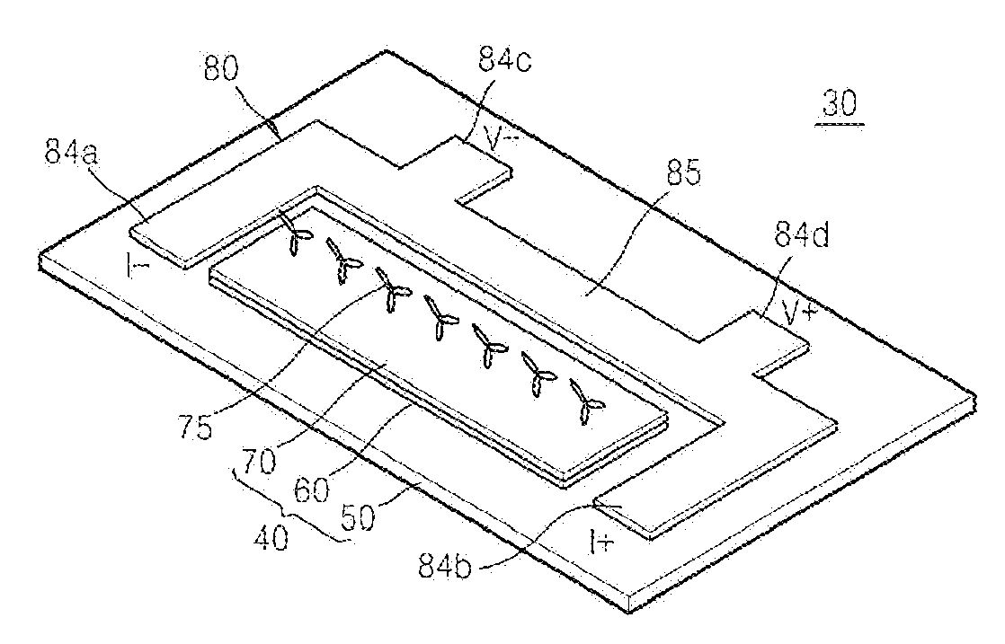
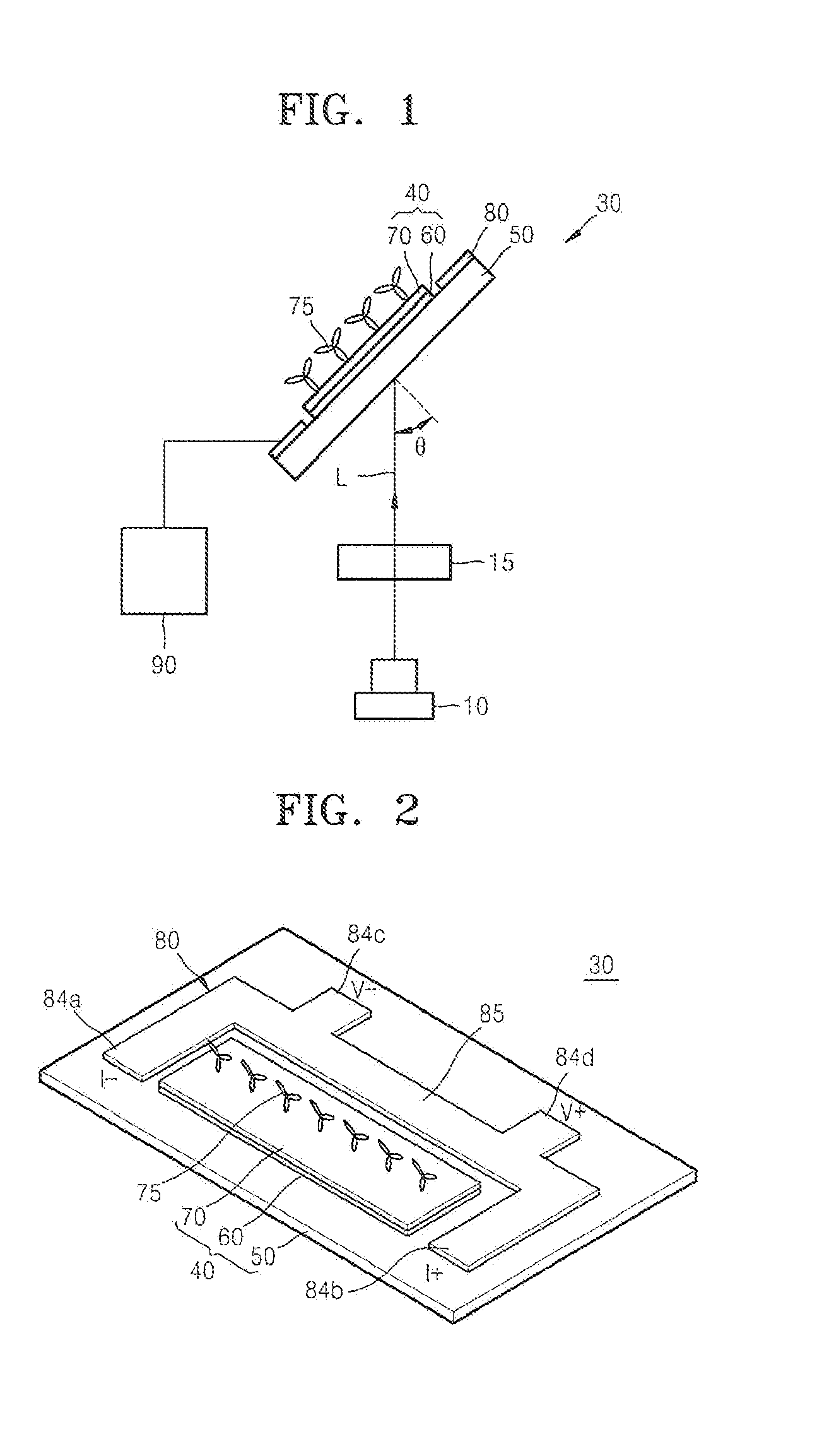
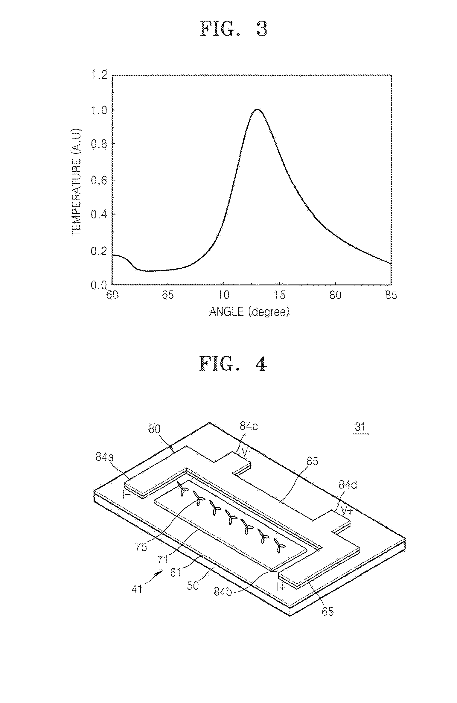
[0030]FIG. 1 schematically illustrates an apparatus for detecting a surface plasmon resonance according to an embodiment of the present disclosure. FIG. 2 is a perspective ...


PUM


Abstract

Disclosed are an apparatus and a method for detecting a surface plasmon resonance. The apparatus may radiate a polarized beam of light to a device, such as a surface plasmon resonance generator, and may measure variations in a temperature of the device to detect whether a surface plasmon resonance has occurred. The detection of a surface plasmon resonance may be associated with the presence of a particular material such as volatile organic compounds (VOCs) or materials disrupting ozone, for example.

Description

CROSS-REFERENCE TO RELATED PATENT APPLICATION[0001]This application claims the benefit of Korean Patent Application No. 10-2008-0129396, filed on Dec. 18, 2008, in the Korean Intellectual Property Office, the disclosure of which is incorporated herein by reference in its entirety.TECHNICAL FIELD[0002]The present disclosure generally relates to an apparatus and a method for detecting a surface plasmon resonance, and more particularly, to an apparatus and a method for detecting a surface plasmon resonance employing a simpler detection structure.BACKGROUND OF RELATED ART[0003]As environmental regulations have been strengthened throughout the world, there is a growing interest in the measurement and removal of harmful materials such as volatile organic compounds (VOCs) or materials disrupting ozone. Thus, many technologies have been developed to measure such harmful materials. Among these technologies, measurements using a surface plasmon resonance have shown to have high sensitivity an...

Claims


Application Information

Patent Timeline
IPC IPC(8): G01N21/55
CPCG01N21/554G01N21/552G01K7/02G01N21/00
Inventor CHOI, SUN-ROCKKIMOH, SEUNG-JINKIM, JOO-HOKIM, WOO-KYU
Owner SAMSUNG ELECTRONICS CO LTD
Why Eureka
Eureka Blog
Learn More