Image diagnosis apparatus and image diagnosis method

a technology of image diagnosis and image, applied in the field of image diagnosis apparatus and image diagnosis method, can solve the problems of physical offset between slices, inability to prevent positional offsets, and inability to simultaneously obtain pet images and ct images, etc., and achieve the effect of accurate correction of positional offsets

Inactive Publication Date: 2010-06-24
KK TOSHIBA +1
View PDF4 Cites 13 Cited by
  • Summary
  • Abstract
  • Description
  • Claims
  • Application Information

AI Technical Summary

Benefits of technology

[0011]It is an object of the present invention to provide an image diagnosis apparatus and image diagnosis method which can accurately correct the positional offset between a PET image and a CT image.

Problems solved by technology

The PET-CT apparatus, however, does not simultaneously obtain a PET image and a CT image.
Furthermore, the inaccuracy of apparatus installation or the like may cause a physical offset between a slice of a PET image and a slice of a CT image.
In some cases, the above methods cannot sufficiently prevent positional offsets.
Even if a respiration protocol with small positional offsets is used, it may not provide sufficient effect.
Alternatively, it may not be possible for a subject to execute a required breathing method.
Furthermore, the correction method which physically measures a positional offset amount may not be able to perform accurate positioning because of insufficient PET position resolution (about 5 mm) and the like.
As described above, although various methods have been provided to solve the problem of the positional offsets between PET images and CT images, the methods do not function effectively in some cases.
In addition, there are neither means nor indexes for quantitative measurement of positional offsets between PET images and CT images.

Method used


Image

  • Image diagnosis apparatus and image diagnosis method
  • Image diagnosis apparatus and image diagnosis method
  • Image diagnosis apparatus and image diagnosis method

Examples


first embodiment

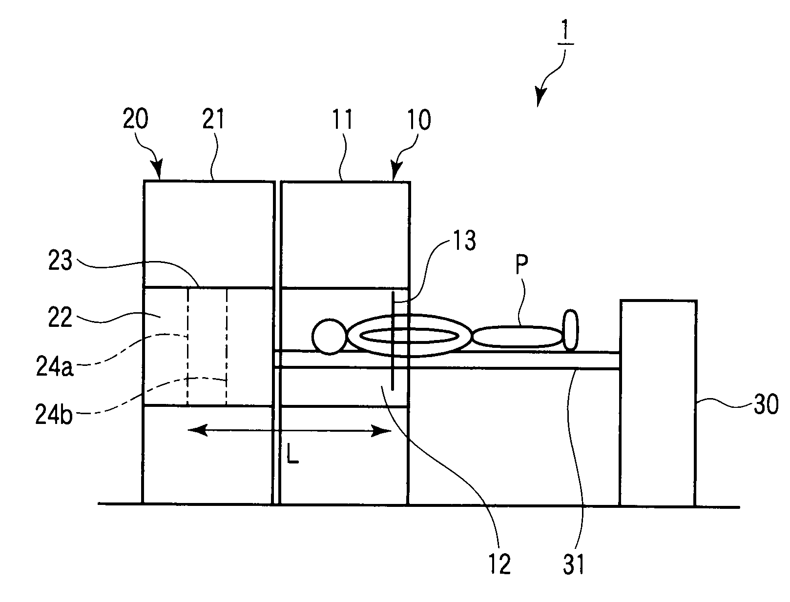
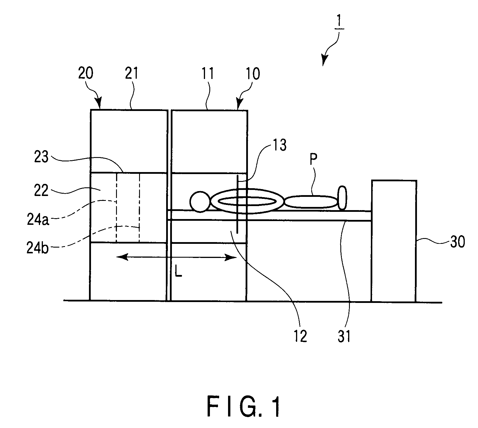
[0030]FIG. 1 is a side view schematically showing the outer appearance of an image diagnosis apparatus (PET-CT apparatus) 1 according to the first embodiment of the present invention.

[0031]As shown in FIG. 1, the image diagnosis apparatus 1 includes an X-ray CT (Computed Tomography) apparatus 10, a PET (Positron Emission Tomography) apparatus 20, and a bed apparatus 30.

[0032]The X-ray CT apparatus 10 is equipped with a CT gantry 11. The PET apparatus 20 is equipped with a PET gantry 21. The CT gantry 11 and the PET gantry 21 are arranged adjacent to each other, with a predetermined positional relationship between them being held, so as to be separably coupled to each other. A hollow portion 12 is formed in the CT gantry 11. A hollow portion 22 is formed in the PET gantry 21. The CT gantry 11 and the PET gantry 21 are arranged such that the center line of the hollow portion 12 almost coincides with the center line of the hollow portion 22.

[0033]The X-ray CT apparatus 10 and the PET a...

second embodiment

[0104]The second embodiment of the present invention will be described next. Note that the same reference numerals as in the first embodiment denote constituent elements having almost the same functions in the second embodiment, and a repetitive description will be made only when required.

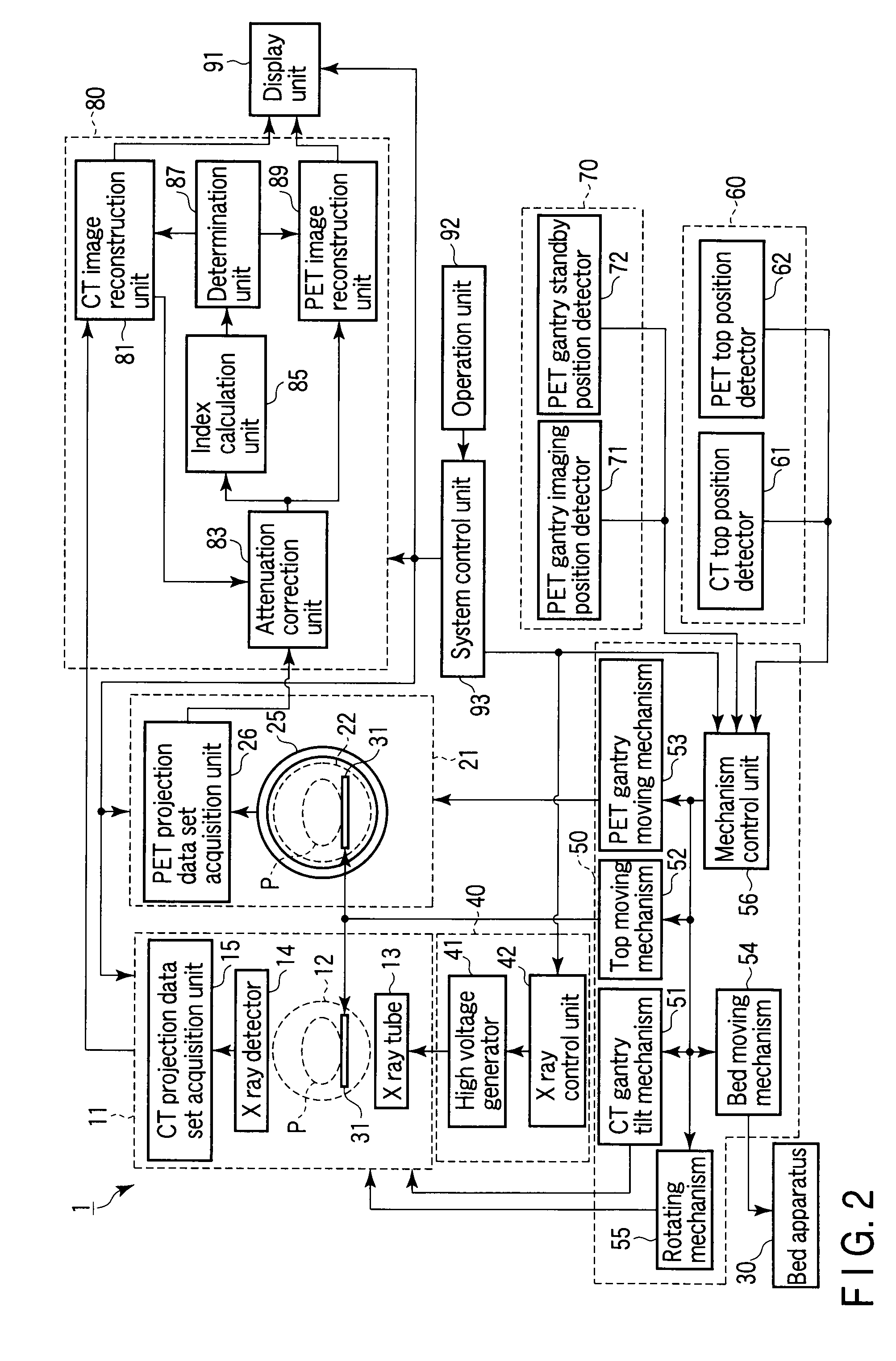
[0105]FIG. 12 is a system block diagram of an image diagnosis apparatus 2 according to the second embodiment. As shown in FIG. 12, an image generating unit 800 of the image diagnosis apparatus 2 includes a CT image reconstruction unit 81, an attenuation correction unit 83, an index calculation unit 85, and a PET image reconstruction unit 89. As is obvious from the comparison with FIG. 2, the image generating unit 800 according to the second embodiment does not include the determination unit 87 included in the image generating unit 80 according to the first embodiment.

[0106]The CT image reconstruction unit 81 reconstructs a CT image. The CT image data is supplied to the attenuation correction unit 8...


PUM


Abstract

A detector detects gamma-rays emitted from inside an imaging region. An acquisition unit acquires a plurality of first projection data sets associated with a plurality of projection angles via the detector. An attenuation-correction unit attenuation-correct the plurality of first projection data sets based on a first CT image associated with the imaging region to generate a plurality of second projection data sets associated with the plurality of projection angles. An index calculation unit calculates an index based on the plurality of second projection data sets. The index is corresponding to a degree of positional offset between the imaging region at the time of acquisition of a plurality of third projection data sets associated with the first CT image and the imaging region at the time of acquisition of the plurality of first projection data sets.

Description

CROSS-REFERENCE TO RELATED APPLICATIONS[0001]This application is based upon and claims the benefit of priority from prior Japanese Patent Application No. 2008-328027, filed Dec. 24, 2008, the entire contents of which are incorporated herein by reference.BACKGROUND OF THE INVENTION[0002]1. Field of the Invention[0003]The present invention relates to an image diagnosis apparatus and image diagnosis method which perform image diagnosis by combining PET (Positron Emission Tomography) and X-ray CT (Computed Tomography).[0004]2. Description of the Related Art[0005]There is available an image diagnosis apparatus (to be referred to as a PET-CT apparatus hereinafter) which performs image diagnosis by combining PET and X-ray CT. A PET-CT apparatus is an apparatus integrating a PET apparatus with an X-ray CT apparatus by using the same bed. The PET-CT apparatus is set to make a slice of a PET image physically match with a slice of a CT image.[0006]The PET-CT apparatus, however, does not simult...

Claims


Application Information

Patent Timeline
Patent Type & Authority Applications(United States)
IPC IPC(8): G06K9/00
CPCA61B6/032A61B6/037A61B6/583G01T1/00G06T11/005A61B6/5235
Inventor MOTOMURA, NOBUTOKUKINDA, AKIYOSHI
Owner KK TOSHIBA
Why Eureka
Try Eureka