Card connector with double cam

a card connector and double cam technology, applied in the direction of coupling device connection, conveying record carriers, instruments, etc., can solve the problems of data damage, short moving distance of memory cards, and inability to recover, so as to reduce manufacturing costs and simplify the structure. , the effect of reducing the siz

Inactive Publication Date: 2010-06-24
MOLEX INC
View PDF2 Cites 14 Cited by
  • Summary
  • Abstract
  • Description
  • Claims
  • Application Information

AI Technical Summary

Benefits of technology

[0016]In accordance with the present invention, the card connector is configured in a manner such that a card is ejected after pushing actions are performed a plurality of times, and a card ejecting action detecting switch is provided for detecting start of card ejection during the forward stroke of the card by the pushing action of the first time. Therefore, the card connector can be of a simpler structure resulting in contribution to a reduction in the manufacturing cost, can bring about reduction in its size, and can provide a sufficiently long delay time to ensure appropriate detection of a card ejecting action.

Problems solved by technology

Therefore, the data might be damaged, or the computing means may stop operating and never recover.
However, in some so-called “push-in / push-out” or “push-push” type of card connectors which are used with a relatively small card, the moving distance of a memory card is short because of the small size, and therefore it is difficult to secure a sufficient length of delay time that starts from a pushing action to eject a memory card and ends when the terminals of the card connector and the contact pads of the memory card are disconnected from each other.
Nevertheless, the conventional card connector failed to take into consideration the use of a delay switch and thus, could not secure a sufficient length of time for removing a memory card from the housing.

Method used


Image

  • Card connector with double cam
  • Card connector with double cam
  • Card connector with double cam

Examples


Embodiment Construction

[0033]Preferred embodiments of the present invention will be described below in detail with reference to the accompanying drawings.

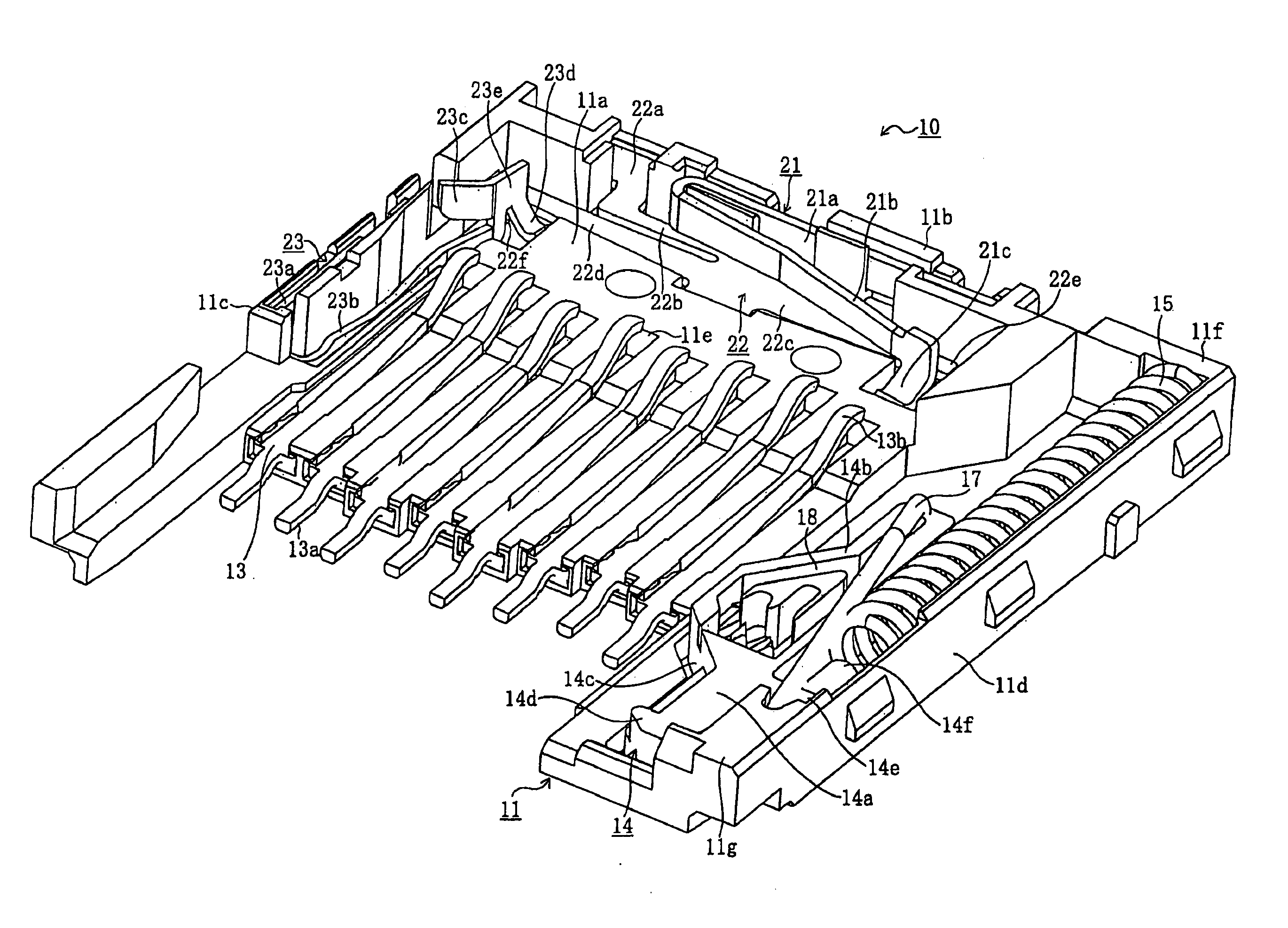
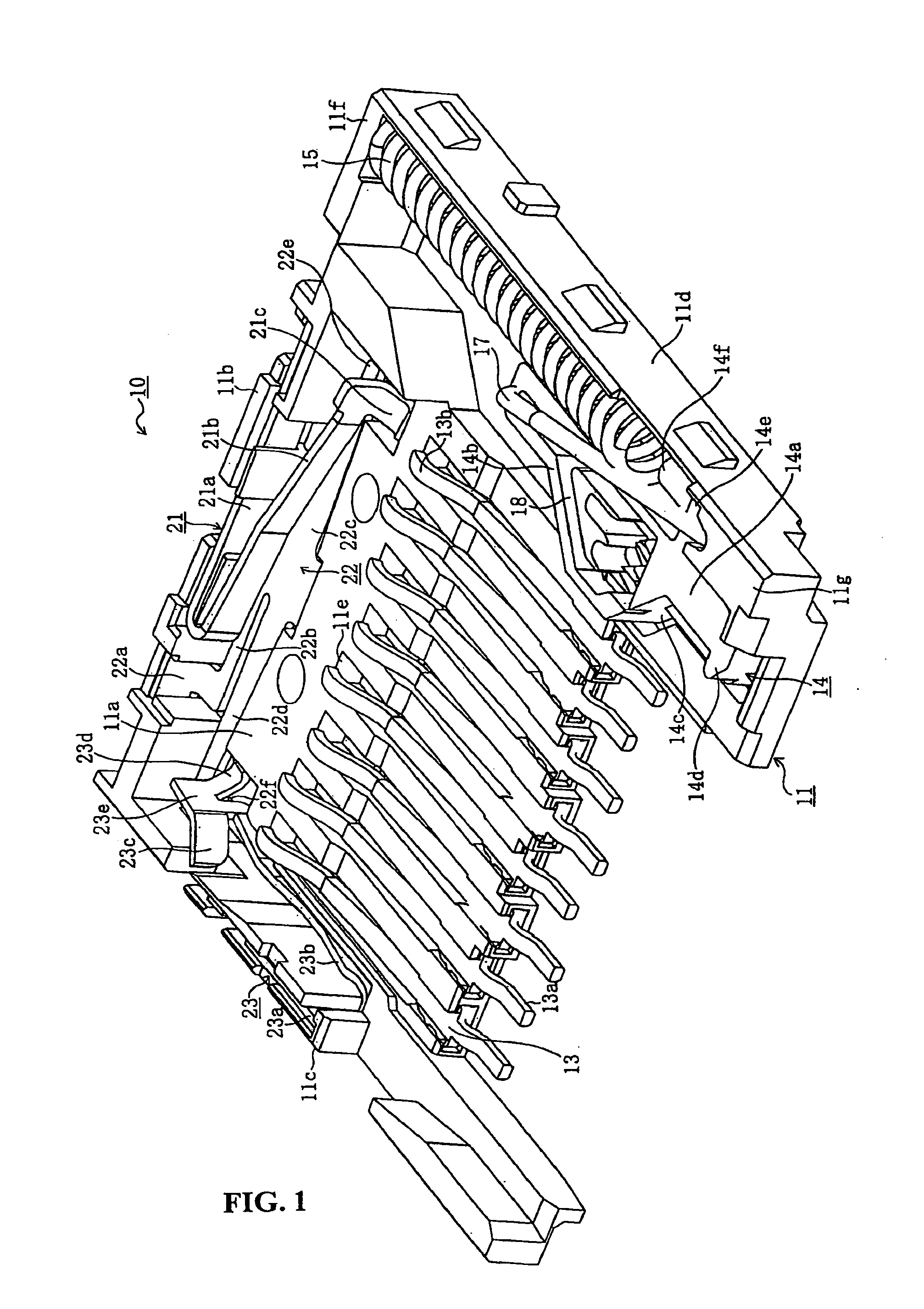
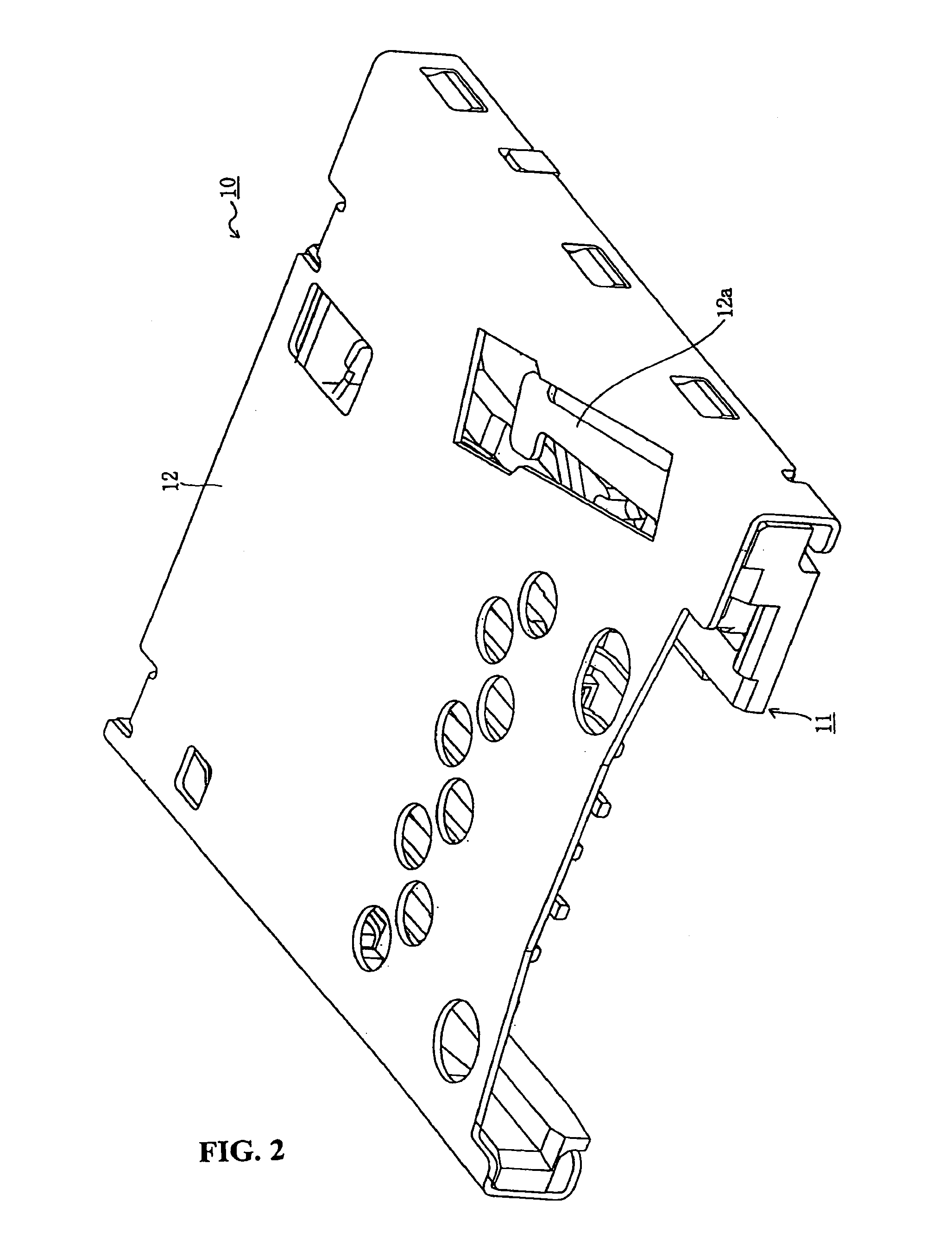
[0034]FIG. 1 is a perspective view showing a card connector without a shell according to an embodiment of the present invention, FIG. 2 is a perspective view showing the card connector according to the embodiment of the present invention, FIG. 3 is a plan view showing the bottom face of a card according to the embodiment of the present invention, FIG. 4 is a perspective view showing a first contact member according to the embodiment of the present invention, FIG. 5 is a perspective view of a shared contact member according to the embodiment of the present invention, and FIG. 6 is a perspective view showing a second contact member according to the embodiment of the present invention.

[0035]In these drawing figures, reference numeral 10 denotes a card connector according to the present embodiment, and is secured to an electronic device (not shown). A card 3...


PUM


Abstract

A card connector includes a housing having a receptacle to receive therein a card in an insertion direction and the card has a terminal member. A connection terminal is secured to the housing and is configured to contact the terminal member of the card. A card ejecting action detecting switch is configured to detect when the card is ejected from the housing. A card guide mechanism is provided with an urging member for urging the card in a direction opposite the insertion direction. The card guide mechanism is configured to hold the card at a locked position to ensure that the terminal member of the card is in contact with the connection terminal and to permit movement of the card in the opposite direction by a pushing force exerted on the card in the insertion direction. The card guide mechanism ejects the card after performing a pushing action on the card a plurality of times.

Description

BACKGROUND OF THE INVENTION[0001]The present invention relates to a card connector. Conventionally, electronic devices such as personal computers, portable phones, PDAs (Personal Digital Assistants), digital cameras, video cameras, music players, game machines, and vehicular navigation systems are quipped with connectors for cards so that various memory cards such as SIM (Subscriber Identity Module) cards, MMC® (Multi Media Cards), SD® (Secure Digital) cards, mini SD® cards, Memory Stick®, and Smart Media® can be used.[0002]In this case, it might be considered to use a delay switch for detecting an early stage of motion to withdraw a card mounted in the above-described electronic device from the device. For example, if a memory card is withdrawn from an electronic device while a computing means of the electronic device is accessing to the memory card to execute a process, a data bus which connects the computing means and the memory card is disconnected in the middle of the data tran...

Claims


Application Information

Patent Timeline
Patent Type & Authority Applications(United States)
IPC IPC(8): H01R13/62
CPCG06K13/08G06K13/0856G06K13/0806H01R12/51H01R13/62G06K19/07
Inventor IDA, AYAKOTAKASE, HISATOMIYAZAWA, JUNICHITEZUKA, AKIHIRONAGASAWA, HIDEOKASAHARA, KATSUNORI
Owner MOLEX INC
Why Eureka
Try Eureka