
BODY-WORN SYSTEM FOR MEASURING CONTINUOUS NON-INVASIVE BLOOD PRESSURE (cNIBP)

a non-invasive, body-worn technology, applied in the direction of bioelectric signal measurement, medical science, diagnostics, etc., can solve the problems of no longer measurable ptt and amplitude of ppg waveform, and achieve fast and comfortable, low cost, and low cost

Active Publication Date: 2010-06-24
SOTERA WIRELESS
View PDF104 Cites 104 Cited by
  • Summary
  • Abstract
  • Description
  • Claims
  • Application Information

AI Technical Summary

Benefits of technology

The invention is a technique for continuous measurement of blood pressure (cNIBP) using a body-worn monitor that measures cNIBP based on the pressure-dependent and pressure-free measurements. The monitor features a wrist-worn transceiver that receives and processes signals from sensors placed on the patient's arm and chest. The monitor wirelessly transmits the information to a remote monitor or device. The technique uses a composite method that takes into account the pressure-dependent and pressure-free measurements, and algorithms to improve accuracy. The monitor also includes a pneumatic system to apply pressure to an artery and measures the resulting pressure waveform. The pressure-dependent measurement is faster and more comfortable compared to the deflation-based measurement.

Problems solved by technology

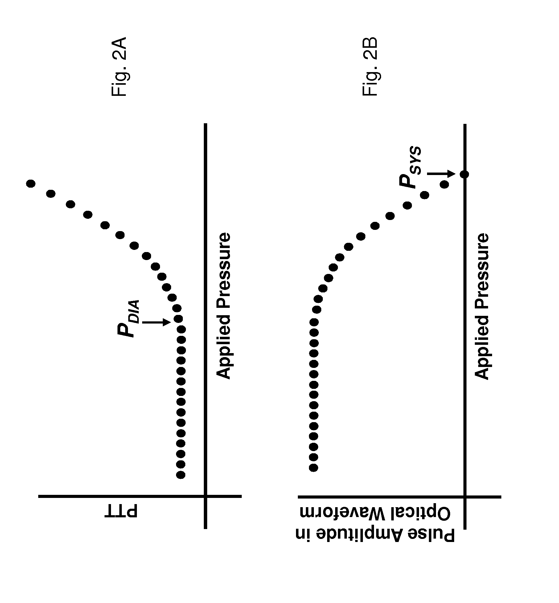
Moreover, when the applied pressure equals systolic blood pressure, the amplitude of the PPG waveform is completely eliminated, and PTT is no longer measurable.

Method used


Image

  • BODY-WORN SYSTEM FOR MEASURING CONTINUOUS NON-INVASIVE BLOOD PRESSURE (cNIBP)
  • BODY-WORN SYSTEM FOR MEASURING CONTINUOUS NON-INVASIVE BLOOD PRESSURE (cNIBP)
  • BODY-WORN SYSTEM FOR MEASURING CONTINUOUS NON-INVASIVE BLOOD PRESSURE (cNIBP)

Examples


Embodiment Construction

Theory of the Composite Method

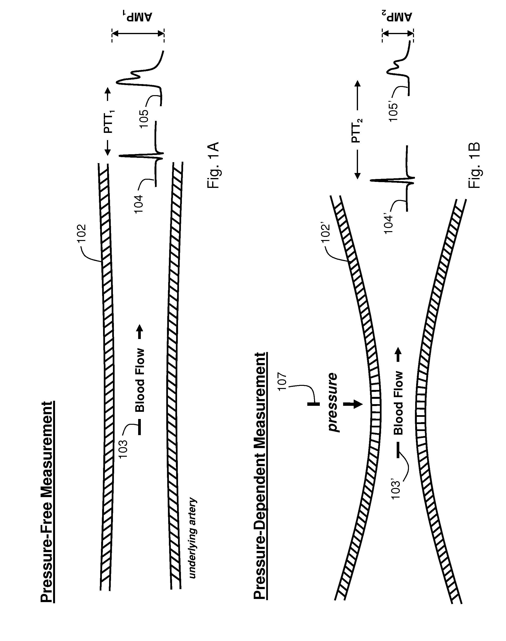
[0060]FIGS. 1A and 1B show schematic drawings of the Composite Method's pressure-free (FIG. 1A) and pressure-dependent (FIG. 1B) measurements. Working in concert, these measurements accurately determine the patient's cNIBP for an extended time without requiring an external calibration device, e.g., a conventional blood pressure cuff. During a measurement, the patient wears a body-worn monitor attached to a disposable cuff and collection of optical, electrical, motion, and temperature sensors. These sensors measure signals for both the pressure-dependent and pressure-free measurements. The co-pending patent applications, the contents of which are fully incorporated herein by reference, describe earlier embodiments of this measurement: DEVICE AND METHOD FOR DETERMINING BLOOD PRESSURE USING ‘HYBRIDPULSE TRANSIT TIME MEASUREMENT (U.S. Ser. No. 60 / 943,464; filed Jun. 12, 2007); VITAL SIGN MONITOR FOR CUFFLESSLY MEASURING BLOOD PRESSURE USING A PULSE TRANSI...


PUM


Abstract

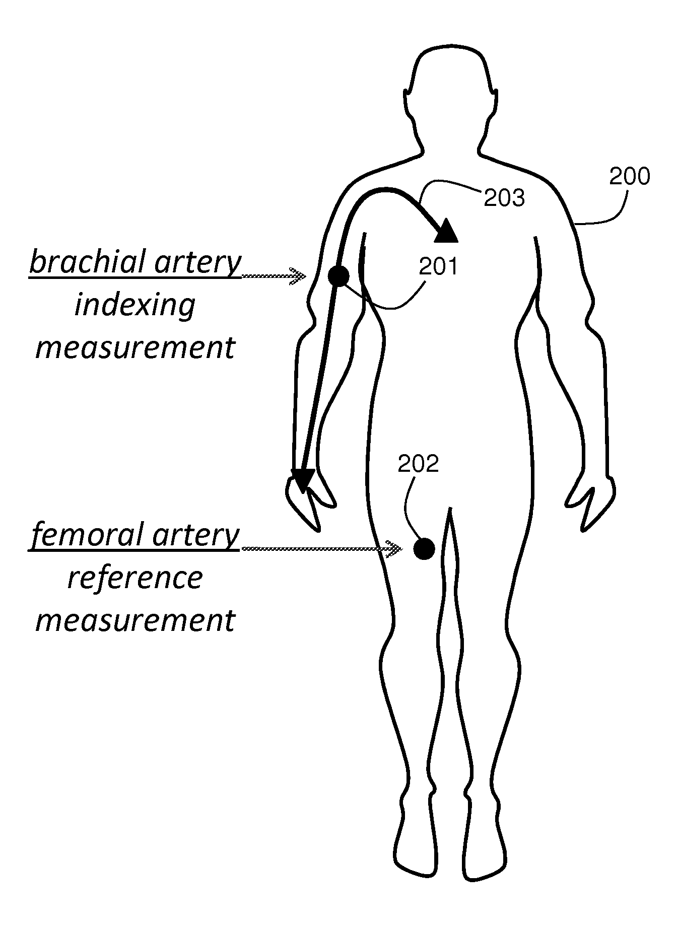
The present invention provides a technique for continuous measurement of blood pressure based on pulse transit time and which does not require any external calibration. This technique, referred to herein as the ‘Composite Method’, is carried out with a body-worn monitor that measures blood pressure and other vital signs, and wirelessly transmits them to a remote monitor. A network of body-worn sensors, typically placed on the patient's right arm and chest, connect to the body-worn monitor and measure time-dependent ECG, PPG, accelerometer, and pressure waveforms. The disposable sensors can include a cuff that features an inflatable bladder coupled to a pressure sensor, three or more electrical sensors (e.g. electrodes), three or more accelerometers, a temperature sensor, and an optical sensor (e.g., a light source and photodiode) attached to the patient's thumb.

Description

CROSS REFERENCES TO RELATED APPLICATIONS[0001]This application is a Continuation-in-Part of co-pending U.S. patent application Ser. No. 12 / 138,194, filed Jun. 12, 2008, entitled VITAL SIGN MONITOR FOR MEASURING BLOOD PRESSURE USING OPTICAL, ELECTRICAL, AND PRESSURE WAVEFORMS, which claims the benefit of U.S. Provisional Application No. 60 / 943,464, filed Jun. 12, 2007, and of U.S. Provisional Application No. 60 / 983,198, filed Oct. 28, 2007; all of which are incorporated herein by reference.BACKGROUND OF THE INVENTION[0002]Pulse transit time (PTT), defined as the transit time for a pressure pulse launched by a heartbeat in a patient's arterial system, has been shown in a number of studies to correlate to both systolic and diastolic blood pressure. In these studies, PTT is typically measured with a conventional vital signs monitor that includes separate modules to determine both an electrocardiogram (ECG waveform) and pulse oximetry (SpO2). During a PTT measurement, multiple electrodes...

Claims


Application Information

Patent Timeline
Patent Type & Authority Applications(United States)
IPC IPC(8): A61B5/021
CPCA61B5/02125A61B5/02133A61B5/0225A61B5/02416A61B5/0452A61B5/1118A61B5/742A61B5/6824A61B5/7239A61B5/0022A61B5/0295A61B5/0402A61B5/14551A61B5/349A61B5/721A61B5/33
Inventor BANET, MATTDHILLON, MARSHALMCCOMBIE, DEVIN
Owner SOTERA WIRELESS
Learn More