Al technical title is built by PatSnap Al team. It summarizes the technical point description of the patent document.
a control valve and fluid technology, applied in the field of fluid regulation, can solve the problems of fluid pressure loss to the fluid being throttled, vibration and noise problems, and occurrence of “noise” to prevent fluid communication
Active Publication Date: 2010-07-01
DRESSER LLC
View PDF17 Cites 22 Cited by
Summary
Abstract
Description
Claims
Application Information
AI Technical Summary
This helps you quickly interpret patents by identifying the three key elements:
Problems solved by technology
Method used
Benefits of technology
[0012]The valve may further include a seat adjacent the body, where the seat may be adapted to contact the throttling ball and substantially prevent fluid communication between the external surface of the throttling ball and the interior cavity. The throttli...
Problems solved by technology
However, at a low flow rate, the bore in the valve element may be substantially out of alignment with the bores in the valve inlet and valve outlet so as to restrict flow through the valve.
When the bore in the valve element is out of alignment with the bores in the inlet and outlet of the valve body, the valve is in a throttling position restricting flow through the valve, which may introduce a loss of fluid pressure to the fluid being throttled.
Localized high-pressure drops may cause vibration and noise problems.
For example, one problem associated with the throttling of pipeline flows with valves is the occurrence of “noise,” which is ca...
Method used
Image
Click on the blue label to locate the original text in one second.
Reading with bidirectional positioning of images and text.
Examples
Embodiment Construction
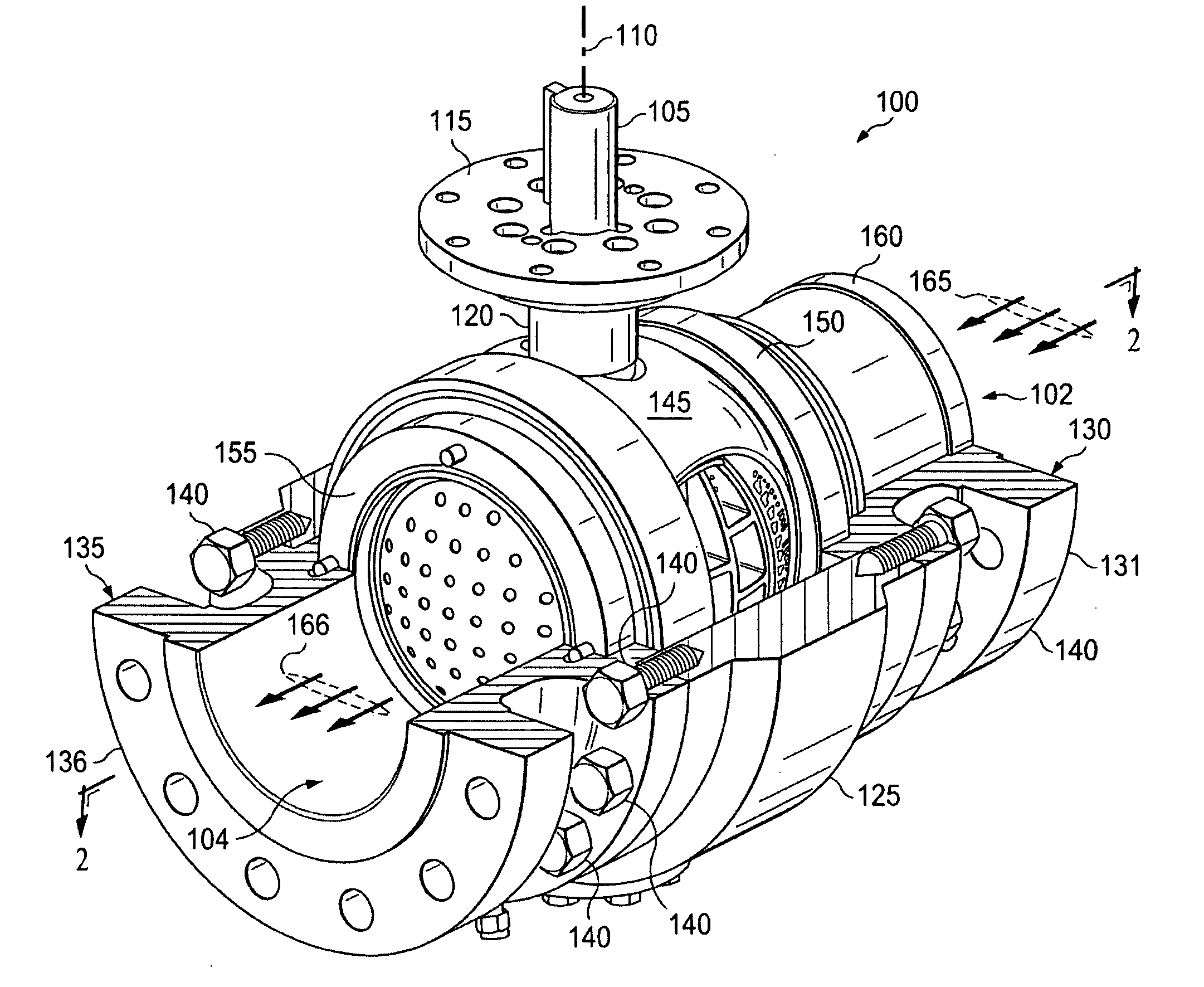
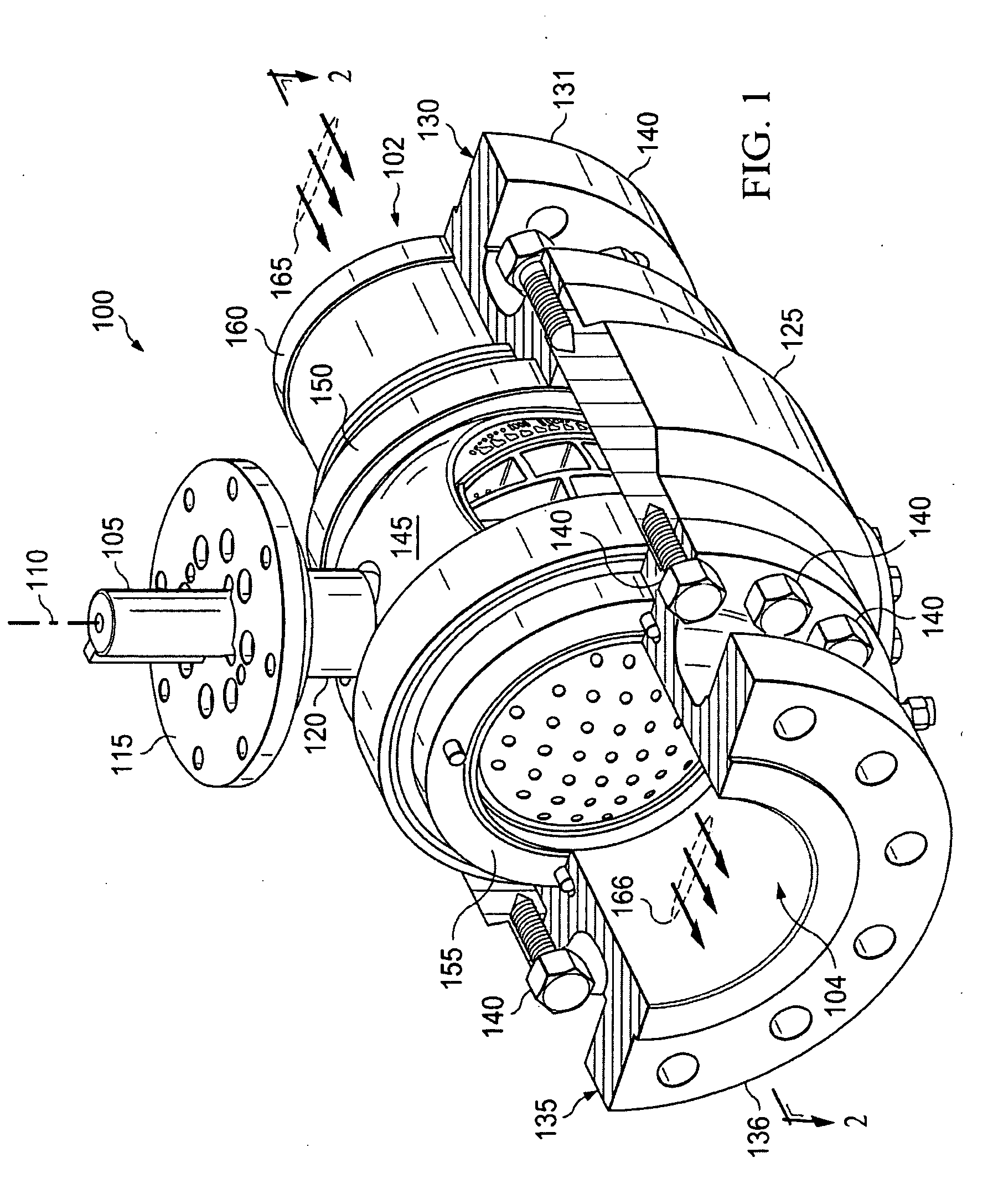
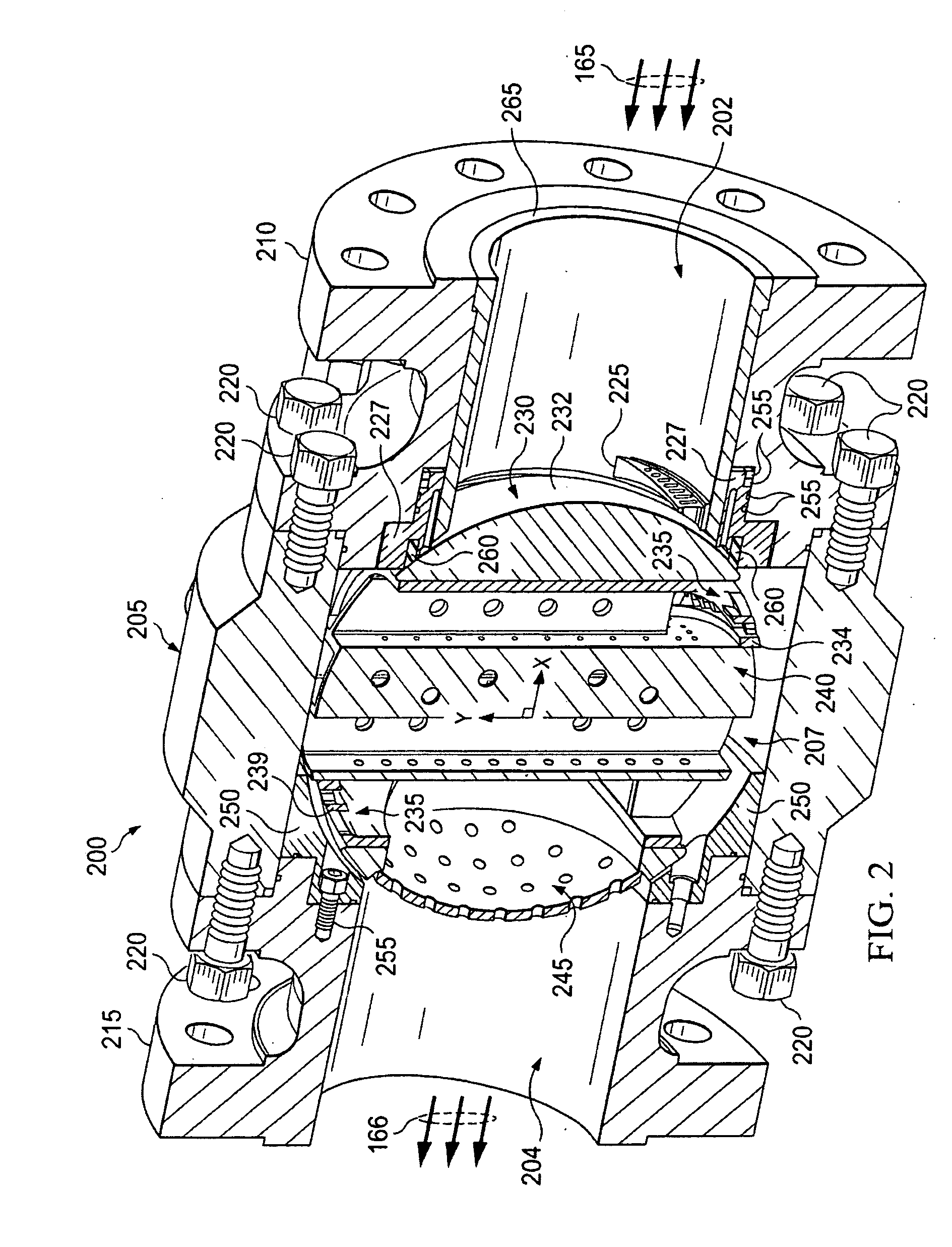
[0031]Fluid regulation may be accomplished by a variety of different methods and devices, such as ball valves. The present disclosure relates to a ball valve with multiple stages of fluid pressure reduction. The ball valve includes a throttling ball disposed within the valve body, including a ball diffuser and internal trim element allowing fluid communication there through. The ball diffuser includes one or more diffuser plates with flow apertures that allow fluid communication there through to a flow plate of the internal trim. Fluid communication through a plurality of orifices disposed through the flow plate is substantially orthogonal to the fluid communication through the diffuser plates. The ball valve further includes a shoe that may be secured to the valve body or a closure element of the valve. The shoe includes a fluid inlet immediately adjacent at least a portion of the throttling ball and proximate to a fluid outlet of the valve body. The shoe also includes a fluid outl...
PUM
Abstract
A valve includes a body, a throttling ball, and a shoe. The body includes an upstream flow passage and a downstream flow passage in fluid communication with an interior cavity of the body. The throttling ball is rotatable within the interior cavity on an axis to adjust the valve from a closed position to an open position and includes a fluid conduit extending through the throttling ball, where the fluid conduit is alignable with the upstream flow passage and the downstream flow passage. The shoe is disposed in the cavity abutting an interior surface of the cavity and includes a fluid passage there through having an inlet being alignable with the flow conduit of the throttling ball and an outlet being alignable with the downstream flow passage of the body. The interior surface of the shoe is disposed adjacent to and tracking an external surface of the throttling ball.
Description
TECHNICAL FIELD[0001]This disclosure relates to fluid regulation, and more particularly to regulating fluid flow by a ball valve with multiple stages of fluid pressure reduction.BACKGROUND[0002]Fluid systems, such as cooling, heating, petroleum refining, pneumatic or other vapor or gas system, waste water control, or chemical process systems, typically utilize valves to control or otherwise regulate fluid flow. These fluid control devices may include a variety of different types, sizes, and configurations of valves, such as globe valves, ball valves, butterfly valves, and plug valves. Several factors affect the design or choice of fluid control valves for any particular fluid application. As used herein fluid may encompass, liquid, vapor, gas, or a mixture of any of these fluid phases. For example, design consideration such as noise, pressure, and temperature, to name a few, may influence the type, size, and construction of any particular fluid control device chosen for a particular...
Claims
Application Information
Patent Timeline
Application Date:The date an application was filed.
Publication Date:The date a patent or application was officially published.
First Publication Date:The earliest publication date of a patent with the same application number.
Issue Date:Publication date of the patent grant document.
PCT Entry Date:The Entry date of PCT National Phase.
Estimated Expiry Date:The statutory expiry date of a patent right according to the Patent Law, and it is the longest term of protection that the patent right can achieve without the termination of the patent right due to other reasons(Term extension factor has been taken into account ).
Invalid Date:Actual expiry date is based on effective date or publication date of legal transaction data of invalid patent.